Cirkit Designer
Your all-in-one circuit design IDE
Home /
Project Documentation
AC to DC Power Supply with Voltage Regulation and Multimeter Monitoring

Circuit Documentation
Summary of the Circuit
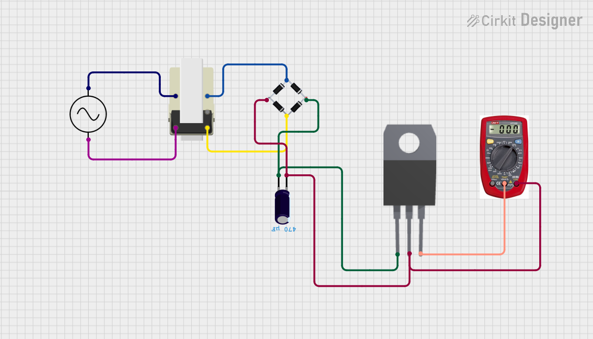
This circuit appears to be a power supply unit that takes an AC input and converts it to a regulated DC output. The AC supply is first stepped down using a transformer, then rectified by a bridge rectifier. The resulting DC is then smoothed by an electrolytic capacitor and regulated by a 7808 voltage regulator to provide a stable 8V DC output. A multimeter is included in the design for measurement purposes.
Component List
Bridge Rectifier
- Description: A bridge rectifier is a device that converts an AC input into a DC output.
- Purpose: To rectify the AC voltage from the transformer to DC.
AC Supply
- Description: An AC supply provides alternating current electricity.
- Purpose: To provide the input AC voltage to the circuit.
Transformer
- Description: A transformer is used to step down or step up the voltage level.
- Purpose: To step down the AC voltage from the AC supply to a lower level suitable for rectification.
Electrolytic Capacitor
- Description: A capacitor that is used to store electrical energy in an electric field.
- Properties: Capacitance of 0.00047 Farads.
- Purpose: To smooth out the rectified DC voltage from the bridge rectifier.
7808 Voltage Regulator
- Description: A voltage regulator that provides a constant 8V output.
- Purpose: To regulate the smoothed DC voltage to a stable 8V output.
Multimeter
- Description: An instrument used to measure electrical properties such as voltage, current, and resistance.
- Purpose: To measure the output voltage and current of the circuit.
Wiring Details
Bridge Rectifier
- Source_in-: Connected to pin 5 of the Transformer.
- Source_out-: Common ground net connecting to the GND of the 7808, the negative pin of the Electrolytic Capacitor, and the COM of the Multimeter.
- Source_out+: Connected to the INPUT of the 7808 and the positive pin of the Electrolytic Capacitor.
- Source_in+: Connected to pin 3 of the Transformer.
AC Supply
- +ve: Connected to pin 1 of the Transformer.
- -ve: Connected to pin 2 of the Transformer.
Transformer
- Pin 5: Connected to Source_in- of the Bridge Rectifier.
- Pin 1: Connected to +ve of the AC Supply.
- Pin 2: Connected to -ve of the AC Supply.
- Pin 3: Connected to Source_in+ of the Bridge Rectifier.
Electrolytic Capacitor
- -: Connected to the common ground net (Source_out- of the Bridge Rectifier, GND of the 7808, COM of the Multimeter).
- +: Connected to Source_out+ of the Bridge Rectifier.
7808 Voltage Regulator
- INPUT: Connected to Source_out+ of the Bridge Rectifier.
- GND: Connected to the common ground net.
- OUTPUT: Connected to the V of the Multimeter.
Multimeter
- COM: Connected to the common ground net.
- V: Connected to the OUTPUT of the 7808.
- A: Not connected in the current configuration.
Documented Code
There is no embedded code provided for any microcontrollers in this circuit. Therefore, this section is not applicable to the current documentation.