Cirkit Designer
Your all-in-one circuit design IDE
Home /
Project Documentation
Arduino-Controlled Automated Irrigation System

Circuit Documentation
Summary
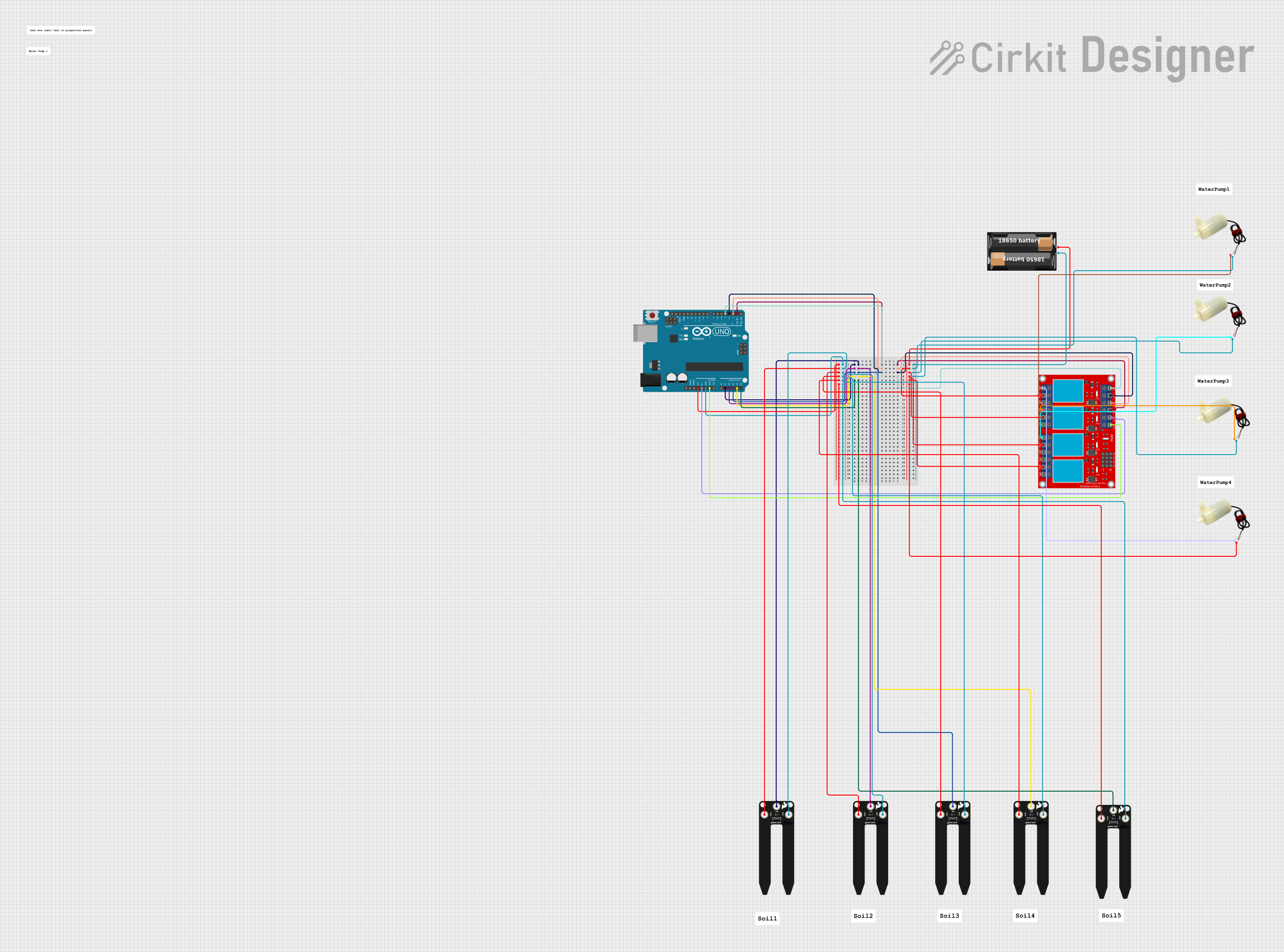
The circuit in question is designed to monitor soil moisture levels using multiple SparkFun gator:soil sensors and control water pumps based on the moisture readings. An Arduino UNO microcontroller serves as the central processing unit, reading sensor data from its analog pins and controlling a 4-channel relay module that powers the water pumps. The relay module is used to switch the water pumps on or off depending on the moisture level detected by the sensors. The system is powered by a battery case.
Component List
Microcontroller
- Arduino UNO: A microcontroller board based on the ATmega328P. It has 14 digital input/output pins, 6 analog inputs, a 16 MHz quartz crystal, a USB connection, a power jack, an ICSP header, and a reset button.
Sensors
- SparkFun gator:soil: A soil moisture sensor that can be used to measure the moisture levels in the soil. It has three pins: VCC, GND, and SIG.
Actuators
- 5v mini water pump: A small water pump that operates at 5 volts. It has two pins: positive and negative.
Power
- My battery case: A case that holds batteries to provide power to the circuit. It has two pins: positive (+) and negative (-).
Relays
- 4 channel relay module: A relay module with four channels that can be used to control high power devices such as the water pumps. It has multiple pins including normally open (N.O.), common (COM), and normally closed (N.C.) contacts for each relay, input pins (IN 1-4), and power pins (VCC+ and VCC-).
Wiring Details
Arduino UNO
- Digital Pins: Connected to the input pins (IN 1-4) of the 4 channel relay module to control the relays.
- Analog Pins (A1-A5): Connected to the SIG pins of the SparkFun gator:soil sensors to read moisture levels.
- 3.3V Pin: Powers the VCC pins of all SparkFun gator:soil sensors.
- 5V Pin: Powers the VCC- (GND) of the 4 channel relay module.
- GND Pins: Common ground for the SparkFun gator:soil sensors and the 4 channel relay module.
SparkFun gator:soil
- SIG Pin: Connected to the corresponding analog pins on the Arduino UNO for moisture level readings.
- VCC Pin: Powered by the 3.3V pin of the Arduino UNO.
- GND Pin: Connected to the ground (GND) of the Arduino UNO.
5v mini water pump
- Positive Pin: Connected to the normally open (N.O.) contacts of the 4 channel relay module.
- Negative Pin: Connected to the negative (-) pin of the battery case.
My battery case
- Positive (+) Pin: Connected to the common (COM) pins of the 4 channel relay module.
- Negative (-) Pin: Connected to the negative pins of the 5v mini water pumps.
4 channel relay module
- IN 1-4 Pins: Controlled by the digital pins (D1-D4) of the Arduino UNO.
- N.O. 1-4 Pins: Connected to the positive pins of the 5v mini water pumps.
- COM 1-4 Pins: Powered by the positive (+) pin of the battery case.
- VCC+ and VCC- Pins: VCC+ connected to the GND of the Arduino UNO, and VCC- connected to the 5V pin of the Arduino UNO.
Documented Code
#include <Wire.h>

int AP2 = A2;
int IN2 = 2;
int moisture = 0;
String moistureString = "";
static const int sensorsTotal = 5;
static const uint8_t analogSensors[] = {A1, A2, A3, A4, A5};
static const int digitalOuts[] = {1, 2, 3, 4, 4};

void setup() {
  Serial.begin(9600);
  pinMode(LED_BUILTIN, OUTPUT);
  digitalWrite(LED_BUILTIN, HIGH);

  for (int i = 0; i < sensorsTotal; i++) {
    pinMode(analogSensors[i], INPUT);
    pinMode(digitalOuts[i], OUTPUT);
  }
  digitalWrite(LED_BUILTIN, LOW);
  Serial.println("Setup complete");
  digitalWrite(IN2, HIGH);
  delay(10000);
}

void loop() {
  digitalWrite(LED_BUILTIN, HIGH);
  for (int i = 0; i < sensorsTotal; i++) {
    moisture = analogRead(analogSensors[i]);
    Serial.print(i + 1);
    Serial.print("-");
    Serial.println(moisture);

    if (moisture > 450) {
      digitalWrite(digitalOuts[i], LOW);
    } else {
      digitalWrite(digitalOuts[i], HIGH);
    }
    moisture = 0;
  }
  digitalWrite(LED_BUILTIN, LOW);
  Serial.println("<><><><><><><>");
  delay(5000);
}
Code Explanation
- The code initializes the serial communication and configures the LED on the Arduino UNO as an output for debugging purposes.
- It sets up the analog sensor pins and digital output pins corresponding to the relay module inputs.
- In the
loopfunction, it reads the moisture level from each sensor and prints it to the serial monitor. - Based on the moisture level, it controls the state of the relays, turning the water pumps on or off.
- The LED blinks to indicate the loop is running, and there is a 5-second delay between each loop iteration.