
Arduino and ESP8266 Automated Climate Control and Lighting System
View and Edit Project In Cirkit Designer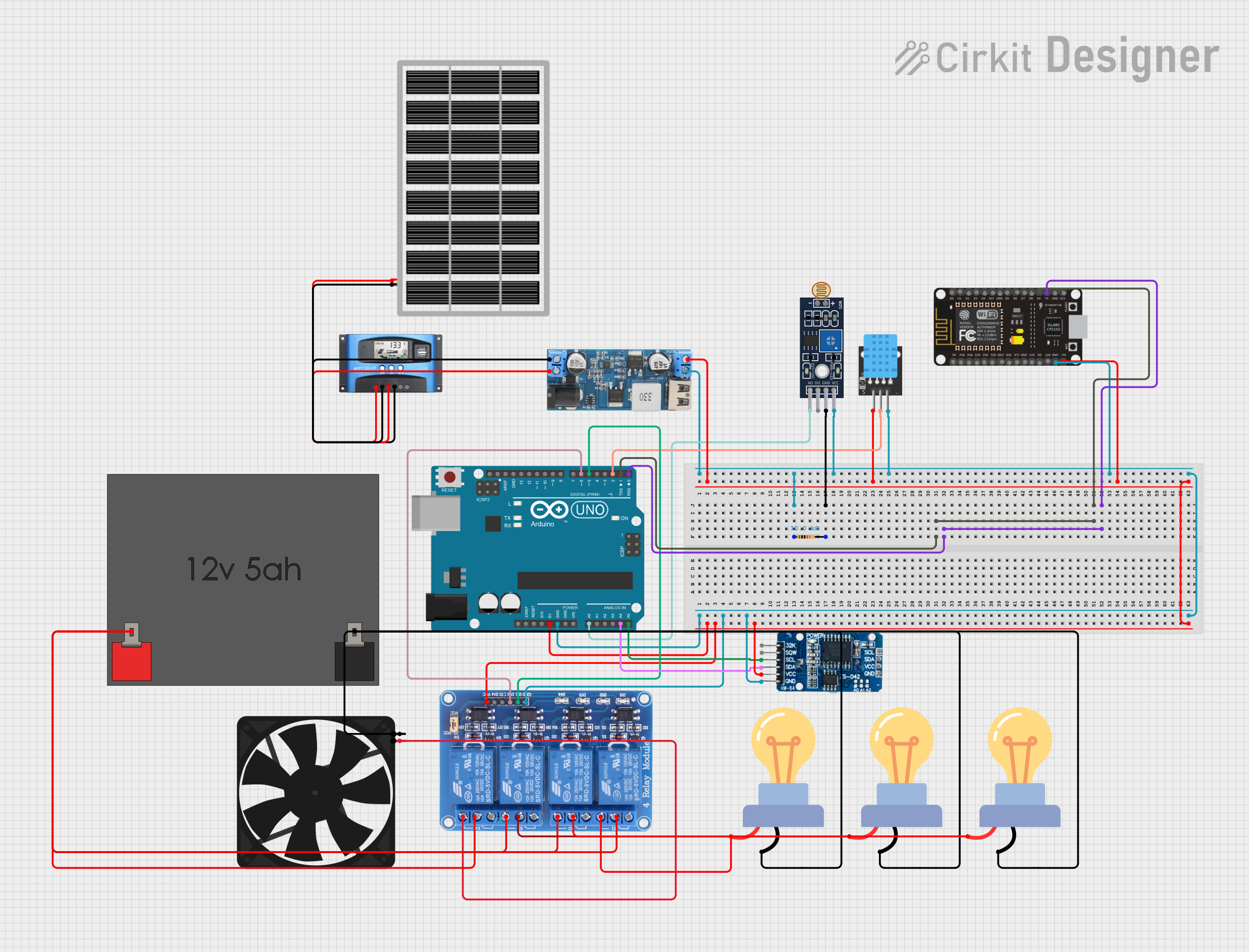
Circuit Documentation
Summary
The circuit is designed to manage and monitor an environment using various sensors and actuators. It includes a solar charge controller for power management, a step-down converter to provide 5V power, temperature and humidity sensing, light level detection, real-time clock tracking, and relay-controlled AC loads such as lights and a fan. Communication with the system is facilitated by an ESP8266 NodeMCU and an Arduino UNO, which also controls the sensors and actuators based on environmental readings and Bluetooth commands.
Component List
MPPT Solar Charge Controller (MPPT SCC)
- Description: Manages power flow from a solar panel to a battery and load.
- Pins: SOLAR+, SOLAR-, BATTERY+, BATTERY-, LOAD+, LOAD-
12V to 5V Step Down Power Converter
- Description: Converts 12V input to a stable 5V output for powering low-voltage devices.
- Pins: VIN 9v-36v, VIN+, VIN-, USB OUTPUT 5V, 5v OUTPUT, GND
KY-015 DHT11 Temperature and Humidity Sensor
- Description: Measures ambient temperature and humidity.
- Pins: 5V, S (Signal), GND
Sensor LDR LM393 Light Sensor
- Description: Measures the intensity of ambient light.
- Pins: A0 (Analog Output), D0 (Digital Output), GND, VCC
Resistor (10k Ohms)
- Description: Provides resistance in the circuit, often used for voltage division or current limiting.
- Pins: pin1, pin2
Relay 4 Channel 5V
- Description: Controls up to four high-power devices, such as AC lights or a fan.
- Pins: GND, IN1, IN2, IN3, IN4, VCC, COM1, COM2, COM3, COM4, NO1, NO2, NO3, NO4, NC1, NC2, NC3, NC4
LED Bulb AC
- Description: An AC-powered light bulb controlled by the relay.
- Pins: +, -
Arduino UNO
- Description: A microcontroller board based on the ATmega328P, used for processing sensor data and controlling the relays.
- Pins: UNUSED, IOREF, Reset, 3.3V, 5V, GND, Vin, A0-A5, SCL, SDA, AREF, D0-D13
ESP8266 NodeMCU
- Description: A Wi-Fi enabled microcontroller for wireless communication.
- Pins: D0-D8, RX, TX, A0, RSV, SD3, SD2, SD1, CMD, SD0, CLK, EN, RST, VIN, 3V3, GND
RTC DS3231 Real-Time Clock
- Description: Keeps track of the current time and date.
- Pins: 32K, SQW, SCL, SDA, VCC, GND
Fan
- Description: An electric fan controlled by the relay.
- Pins: GND, 5V
12V 5Ah Battery
- Description: Provides power storage for the system.
- Pins: 12V +, 12V -
Solar Panel
- Description: Converts sunlight into electrical energy to charge the battery.
- Pins: GND, VCC
Wiring Details
MPPT Solar Charge Controller
- SOLAR+ connected to Solar Panel VCC
- SOLAR- connected to Solar Panel GND
- BATTERY+ connected to 12V to 5V Step Down Power Converter VIN+
- BATTERY- connected to 12V to 5V Step Down Power Converter VIN-
12V to 5V Step Down Power Converter
- VIN 9v-36v not connected
- VIN+ connected to MPPT SCC BATTERY+
- VIN- connected to MPPT SCC BATTERY-
- USB OUTPUT 5V not connected
- 5v OUTPUT connected to Arduino UNO 5V
- GND connected to common ground net
KY-015 DHT11
- 5V connected to Arduino UNO 5V
- S (Signal) connected to Arduino UNO D2
- GND connected to common ground net
Sensor LDR LM393
- A0 connected to Arduino UNO A0
- D0 not connected
- GND connected to common ground net
- VCC connected to Arduino UNO 5V
Resistor (10k Ohms)
- pin1 connected to common ground net
- pin2 connected to Sensor LDR LM393 GND
Relay 4 Channel 5V
- GND connected to common ground net
- IN1 connected to Arduino UNO D5
- IN2 connected to Arduino UNO D6
- IN3 not connected
- IN4 not connected
- VCC connected to Arduino UNO 5V
- COM1 connected to NO1 and LED Bulb AC +
- COM2 connected to LED Bulb AC +
- COM3 connected to LED Bulb AC +
- COM4 connected to common positive net
- NO1 connected to LED Bulb AC +
- NO2 connected to common positive net
- NO3 connected to common positive net
- NO4 connected to Fan 5V
- NC1-NC4 not connected
LED Bulb AC
-
- (three instances) connected to Relay 4 Channel 5V COM1, COM2, and COM3 respectively
-
- (three instances) connected to common negative net
Arduino UNO
- 5V connected to common positive net
- GND connected to common ground net
- A0 connected to Sensor LDR LM393 A0
- A4 (SDA) connected to RTC DS3231 SDA
- A5 (SCL) connected to RTC DS3231 SCL
- D0 (RX) connected to ESP8266 NodeMCU TX
- D1 (TX) connected to ESP8266 NodeMCU RX
- D2 connected to KY-015 DHT11 S
- D5 connected to Relay 4 Channel 5V IN1
- D6 connected to Relay 4 Channel 5V IN2
ESP8266 NodeMCU
- GND connected to common ground net
- VIN connected to Arduino UNO 5V
- RX connected to Arduino UNO D1 (TX)
- TX connected to Arduino UNO D0 (RX)
RTC DS3231
- SDA connected to Arduino UNO A4 (SDA)
- SCL connected to Arduino UNO A5 (SCL)
- VCC connected to Arduino UNO 5V
- GND connected to common ground net
Fan
- 5V connected to Relay 4 Channel 5V NO4
- GND connected to common negative net
12V 5Ah Battery
- 12V + connected to common positive net
- 12V - connected to common negative net
Solar Panel
- VCC connected to MPPT SCC SOLAR+
- GND connected to MPPT SCC SOLAR-
Documented Code
Arduino UNO Code (sketch.ino)
#include <DHT.h>
#include <Wire.h>
#include <RTClib.h>
#include <SoftwareSerial.h>  // For Bluetooth

#define DHTPIN 2       // Pin connected to DHT11
#define DHTTYPE DHT11  // DHT 11 sensor
#define RELAY_LIGHT 3  // Pin connected to Relay for Light
#define RELAY_FAN 4    // Pin connected to Relay for Fan
#define LDR_PIN A0     // Pin connected to LDR
#define PIR_PIN 5      // Pin connected to PIR sensor

DHT dht(DHTPIN, DHTTYPE);  // Initialize DHT sensor
RTC_DS3231 rtc;            // Real-Time Clock instance
SoftwareSerial bluetooth(10, 11);  // RX, TX for Bluetooth

void setup() {
  Serial.begin(9600);  // Start serial communication for debugging
  bluetooth.begin(9600); // Start Bluetooth communication

  // Initialize DHT sensor
  dht.begin();

  // Initialize relays as outputs
  pinMode(RELAY_LIGHT, OUTPUT);
  pinMode(RELAY_FAN, OUTPUT);

  // Initialize PIR sensor as input
  pinMode(PIR_PIN, INPUT);

  // Initialize RTC
  if (!rtc.begin()) {
    Serial.println("Couldn't find RTC");
    while (1);
  }

  if (rtc.lostPower()) {
    // Set RTC to current time
    rtc.adjust(DateTime(F(__DATE__), F(__TIME__)));
  }
}

void loop() {
  // Read temperature and humidity
  float temp = dht.readTemperature();
  float humidity = dht.readHumidity();

  // Check if readings are valid
  if (isnan(temp) || isnan(humidity)) {
    Serial.println("Failed to read from DHT sensor!");
    return;
  }

  // Read LDR value
  int lightLevel = analogRead(LDR_PIN);

  // Read PIR sensor value
  int motionDetected = digitalRead(PIR_PIN);