
Arduino-Controlled Stepper Motor with Wi-Fi Connectivity and Proximity Sensing
View and Edit Project In Cirkit Designer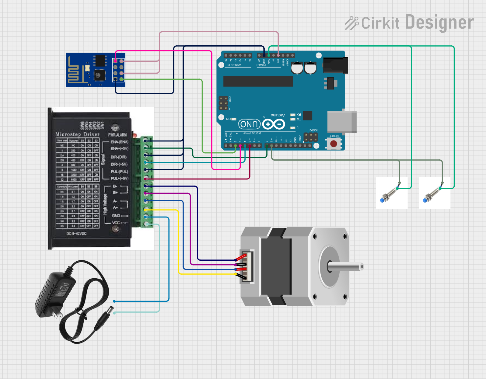
Circuit Documentation
Summary
This circuit integrates a stepper motor controlled by a stepper driver, which is managed by an Arduino UNO microcontroller. The system also includes two proximity sensors for position or distance sensing and an ESP8266 ESP-01 WiFi module for wireless connectivity. A 12V power supply provides the necessary power to the stepper driver and the proximity sensors. The Arduino UNO is responsible for controlling the stepper driver's enable, direction, and pulse signals, as well as reading signals from the proximity sensors and communicating with the ESP8266 module.
Component List
Stepper Driver
- Pins: ENA, ENA-, DIR-, DIR+, PUL-, PUL+, B-, B+, A-, A+, GND, VCC
- Description: Drives the stepper motor based on signals from the Arduino UNO.
Stepper Motor (Bipolar)
- Pins: A, B, C, D
- Description: Bipolar stepper motor that is controlled by the stepper driver.
Arduino UNO
- Pins: UNUSED, IOREF, Reset, 3.3V, 5V, GND, Vin, A0, A1, A2, A3, A4, A5, SCL, SDA, AREF, D13, D12, D11, D10, D9, D8, D7, D6, D5, D4, D3, D2, D1, D0
- Description: Microcontroller used to control the stepper driver, read proximity sensor outputs, and communicate with the ESP8266 WiFi module.
Proximity Sensor
- Pins: GND, +12V
- Description: Sensor used to detect the presence of nearby objects without physical contact.
12V Power Supply
- Pins: +, -
- Description: Provides the 12V power required by the stepper driver and proximity sensors.
ESP8266 ESP-01 WiFi Module
- Pins: TXD, CH_PD, RST, VCC, GND, GPIO_2, GPIO_0, RXD
- Description: WiFi module that enables wireless communication for the Arduino UNO.
Wiring Details
Stepper Driver
- ENA connected to Arduino UNO GND
- ENA- connected to Arduino UNO D8
- DIR- connected to Arduino UNO GND
- DIR+ connected to Arduino UNO D4
- PUL- connected to Arduino UNO GND
- PUL+ connected to Arduino UNO D5
- B- connected to Stepper Motor pin A
- B+ connected to Stepper Motor pin C
- A- connected to Stepper Motor pin B
- A+ connected to Stepper Motor pin D
- GND connected to 12V Power Supply -
- VCC connected to 12V Power Supply +
Stepper Motor (Bipolar)
- A connected to Stepper Driver B-
- B connected to Stepper Driver A-
- C connected to Stepper Driver B+
- D connected to Stepper Driver A+
Arduino UNO
- GND connected to Stepper Driver GND, ESP8266 GND, and both Proximity Sensors GND
- D8 connected to Stepper Driver ENA-
- D4 connected to Stepper Driver DIR+
- D5 connected to Stepper Driver PUL+
- 3.3V connected to ESP8266 CH_PD and VCC
- D9 connected to both Proximity Sensors +12V
- D3 connected to ESP8266 RXD
- D2 connected to ESP8266 TXD
Proximity Sensors
- GND connected to Arduino UNO GND
- +12V connected to Arduino UNO D9
12V Power Supply
-
- connected to Stepper Driver VCC
-
- connected to Stepper Driver GND
ESP8266 ESP-01 WiFi Module
- TXD connected to Arduino UNO D2
- CH_PD connected to Arduino UNO 3.3V
- RST not connected
- VCC connected to Arduino UNO 3.3V
- GND connected to Arduino UNO GND
- GPIO_2 not connected
- GPIO_0 not connected
- RXD connected to Arduino UNO D3
Documented Code
Arduino UNO Code (sketch.ino)
void setup() {
  // put your setup code here, to run once:

}

void loop() {
  // put your main code here, to run repeatedly:

}
Additional Notes (documentation.txt)
No additional code documentation was provided for the Arduino UNO.