
Arduino UNO Based Temperature Monitoring System with MAX6675 and RTC
View and Edit Project In Cirkit Designer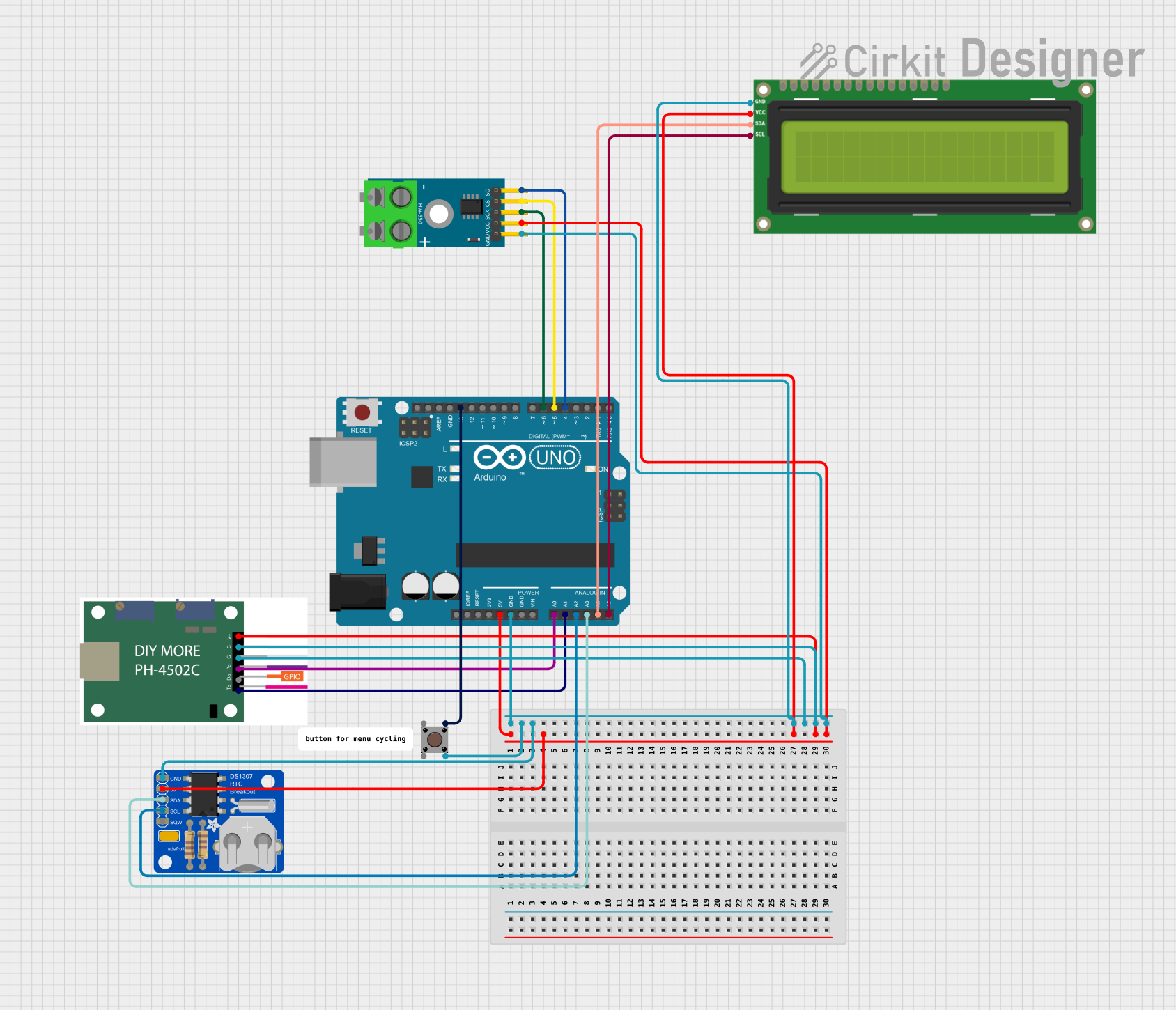
Circuit Documentation
Summary
This circuit integrates various components with an Arduino UNO microcontroller to perform a set of functions that are not explicitly defined by the provided information. The components include a MAX6675 Module for thermocouple temperature readings, a ph4502c sensor module, an I2C LCD 16x2 Screen for display purposes, a Pushbutton for user input, and an Adafruit DS1307 Real Time Clock (RTC) Breakout for timekeeping. The Arduino UNO serves as the central processing unit, interfacing with each module and sensor to collect data, control outputs, and interact with the user.
Component List
Arduino UNO: A microcontroller board based on the ATmega328P. It has digital input/output pins, analog inputs, a USB connection for programming, and power management features.
MAX6675 Module: A thermocouple-to-digital converter that reads temperatures from a K-type thermocouple and outputs the data in a digital format for microcontroller interfacing.
ph4502c: A sensor module, the exact function of which is not specified in the provided information. It has several pins for power, ground, and data outputs.
I2C LCD 16x2 Screen: A liquid crystal display that can show 16 characters per line on 2 lines. It uses the I2C communication protocol for interfacing with the microcontroller.
Pushbutton: A simple switch that allows a user to input a signal to the microcontroller.
Adafruit DS1307 RTC Breakout: A real-time clock module that keeps track of the current time and can be used to perform actions at specific times or intervals.
Wiring Details
Arduino UNO
- 5V: Powers the Adafruit DS1307 RTC, I2C LCD 16x2 Screen, ph4502c, and MAX6675 Module.
- GND: Common ground for Pushbutton, Adafruit DS1307 RTC, I2C LCD 16x2 Screen, ph4502c, and MAX6675 Module.
- A0: Connected to the Po pin of the ph4502c.
- A1: Connected to the To pin of the ph4502c.
- A2: Connected to the SCL pin of the Adafruit DS1307 RTC.
- A3: Connected to the SDA pin of the Adafruit DS1307 RTC.
- A4: Connected to the SDA pin of the I2C LCD 16x2 Screen.
- A5: Connected to the SCL pin of the I2C LCD 16x2 Screen.
- D13: Connected to the Pin 3 (out) of the Pushbutton.
- D6: Connected to the SCK pin of the MAX6675 Module.
- D5: Connected to the CS pin of the MAX6675 Module.
- D4: Connected to the SO pin of the MAX6675 Module.
MAX6675 Module
- GND: Connected to the Arduino UNO GND.
- VCC: Powered by the Arduino UNO 5V.
- SCK: Connected to the Arduino UNO D6.
- CS: Connected to the Arduino UNO D5.
- SO: Connected to the Arduino UNO D4.
ph4502c
- VCC: Powered by the Arduino UNO 5V.
- G1: Connected to the Arduino UNO GND.
- G2: Connected to the Arduino UNO GND.
- Po: Connected to the Arduino UNO A0.
- Do: Not connected in this circuit.
- To: Connected to the Arduino UNO A1.
I2C LCD 16x2 Screen
- SCL: Connected to the Arduino UNO A5.
- SDA: Connected to the Arduino UNO A4.
- VCC (5V): Powered by the Arduino UNO 5V.
- GND: Connected to the Arduino UNO GND.
Pushbutton
- Pin 3 (out): Connected to the Arduino UNO D13.
- Pin 4 (out): Connected to the Arduino UNO GND.
- Pin 1 (in): Not connected in this circuit.
- Pin 2 (in): Not connected in this circuit.
Adafruit DS1307 RTC Breakout
- SQW: Not connected in this circuit.
- SCL: Connected to the Arduino UNO A2.
- SDA: Connected to the Arduino UNO A3.
- VCC: Powered by the Arduino UNO 5V.
- GND: Connected to the Arduino UNO GND.
Documented Code
Arduino UNO Code (sketch.ino)
void setup() {
  // put your setup code here, to run once:

}

void loop() {
  // put your main code here, to run repeatedly:

}
Note: The provided code is a template and does not include any functional code. It is expected that the user will add the necessary setup and loop code to interact with the connected components.