
Arduino and ESP32 Powered Smart Plant Monitoring System with Wi-Fi Connectivity
View and Edit Project In Cirkit Designer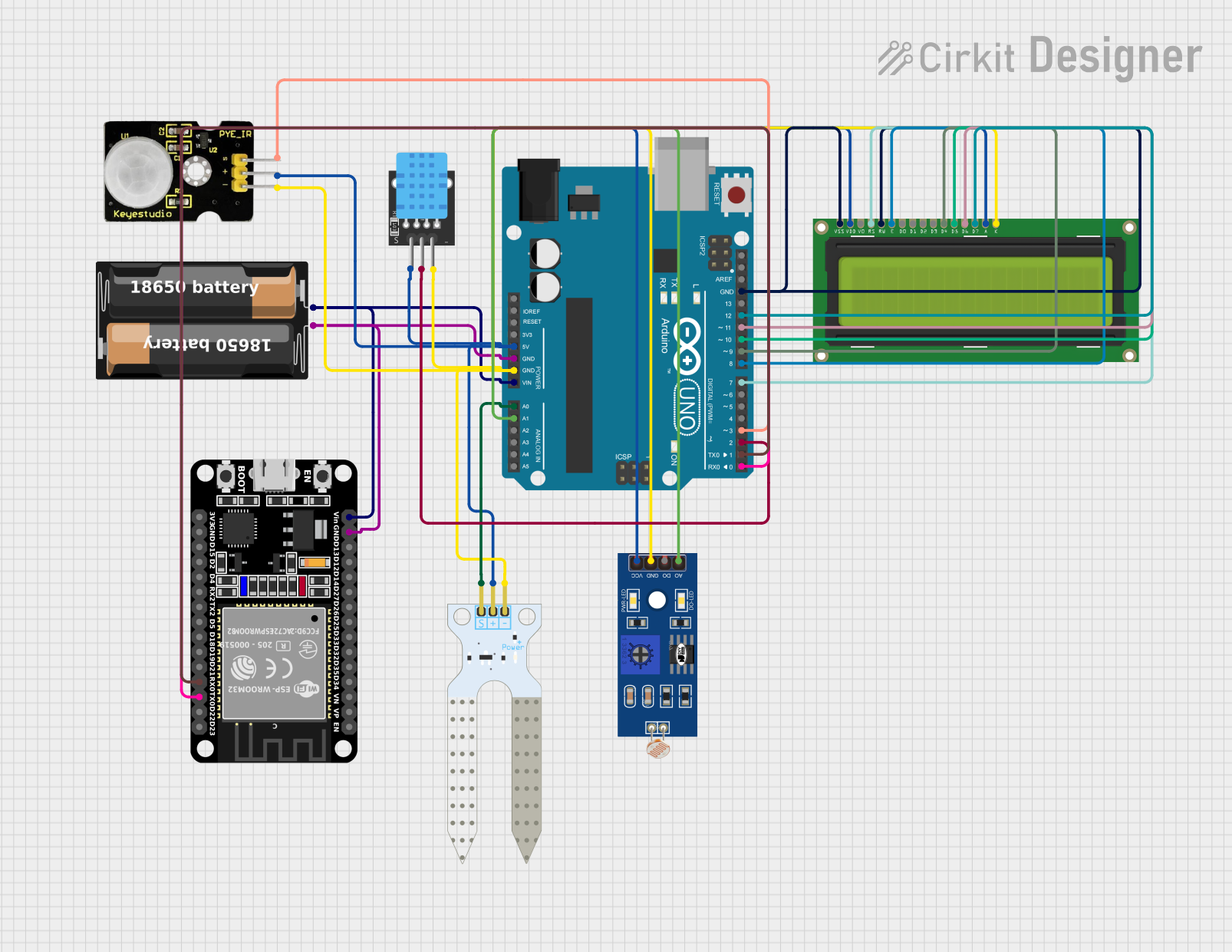
Circuit Documentation
Summary
This circuit is designed to monitor and control environmental parameters for applications such as smart plant systems. It includes sensors for measuring temperature, humidity, soil moisture, and motion detection. The system uses an Arduino UNO as the primary microcontroller for sensor data acquisition and control logic, interfacing with an LCD display for real-time data output. An ESP32 microcontroller is included for wireless communication capabilities, potentially to interface with IoT platforms like Blynk for remote monitoring. A battery case provides power to the system, ensuring portability and ease of deployment.
Component List
Arduino UNO
- Microcontroller board based on the ATmega328P
- Used for controlling sensors, LCD display, and relay
ESP32 (30 pin)
- Microcontroller with Wi-Fi and Bluetooth capabilities
- Used for IoT connectivity and remote data transmission
LCD Display 16x2
- Alphanumeric liquid crystal display
- Displays temperature, humidity, and soil moisture data
My battery case
- Power supply unit for the circuit
- Provides a portable power source
KY-015 DHT11
- Temperature and humidity sensor
- Measures ambient temperature and humidity
Soil Moisture Sensor
- Detects the moisture level in the soil
- Used to monitor and control watering systems
PIR Sensor
- Motion detector sensor
- Detects the presence of humans or animals in the vicinity
LDR (Light Dependent Resistor)
- Measures the intensity of light
- Can be used to monitor environmental light conditions
Wiring Details
Arduino UNO
5Vconnected to LCD Display (LEDA, VDD), KY-015 DHT11 (5V), PIR Sensor (VCC), LDR (VCC), Soil Moisture Sensor (VCC)GNDconnected to ESP32 (GND), My battery case (-), LCD Display (LEDK, RW, VSS), KY-015 DHT11 (GND), PIR Sensor (GND), LDR (GND), Soil Moisture Sensor (GND)Vinconnected to ESP32 (Vin), My battery case (+)A0connected to Soil Moisture Sensor (SIG)A1connected to LDR (A0)D12connected to LCD Display (DB7)D11connected to LCD Display (DB6)D10connected to LCD Display (DB5)D9connected to LCD Display (DB4)D8connected to LCD Display (E)D7connected to LCD Display (RS)D3connected to PIR Sensor (Data)D2connected to KY-015 DHT11 (S)D1connected to ESP32 (RX0)D0connected to ESP32 (TX0)
ESP32 (30 pin)
GNDconnected to Arduino UNO (GND), My battery case (-)Vinconnected to Arduino UNO (Vin), My battery case (+)RX0connected to Arduino UNO (D1)TX0connected to Arduino UNO (D0)
LCD Display 16x2
LEDAandVDDconnected to Arduino UNO (5V)LEDK,RW, andVSSconnected to Arduino UNO (GND)DB7connected to Arduino UNO (D12)DB6connected to Arduino UNO (D11)DB5connected to Arduino UNO (D10)DB4connected to Arduino UNO (D9)Econnected to Arduino UNO (D8)RSconnected to Arduino UNO (D7)
KY-015 DHT11
5Vconnected to Arduino UNO (5V)Sconnected to Arduino UNO (D2)GNDconnected to Arduino UNO (GND)
Soil Moisture Sensor
VCCconnected to Arduino UNO (5V)GNDconnected to Arduino UNO (GND)SIGconnected to Arduino UNO (A0)
PIR Sensor
VCCconnected to Arduino UNO (5V)GNDconnected to Arduino UNO (GND)Dataconnected to Arduino UNO (D3)
LDR
VCCconnected to Arduino UNO (5V)GNDconnected to Arduino UNO (GND)A0connected to Arduino UNO (A1)
Documented Code
Arduino UNO Code
#include <Wire.h>
#include <LiquidCrystal_I2C.h>
#include <DHT.h>

#define DHTPIN 2      // Pin where DHT11 is connected
#define DHTTYPE DHT11
DHT dht(DHTPIN, DHTTYPE);

#define soilMoisturePin A0
#define relayPin 8
#define pirPin 3

LiquidCrystal_I2C lcd(0x27, 16, 2);

void setup() {
  lcd.begin();
  lcd.backlight();

  pinMode(relayPin, OUTPUT);
  pinMode(pirPin, INPUT);

  dht.begin();
  lcd.setCursor(0, 0);
  lcd.print("Smart Plant");
  delay(2000);
}

void loop() {
  float temp = dht.readTemperature();
  float humidity = dht.readHumidity();
  int soilMoistureValue = analogRead(soilMoisturePin);
  int motionDetected = digitalRead(pirPin);

  // Display sensor data on LCD
  lcd.clear();
  lcd.setCursor(0, 0);
  lcd.print("T:"); lcd.print(temp); lcd.print("C");
  lcd.setCursor(0, 1);
  lcd.print("H:"); lcd.print(humidity); lcd.print("%");
  lcd.setCursor(8, 1);
  lcd.print("M:"); lcd.print(soilMoistureValue);

  // Control water pump based on soil moisture
  if (soilMoistureValue < 400) {   // Adjust threshold as needed
    digitalWrite(relayPin, LOW);  // Activate pump (LOW because relay is active LOW)
  } else {
    digitalWrite(relayPin, HIGH);  // Deactivate pump
  }

  delay(2000);  // Wait for 2 seconds before repeating
}
ESP32 Code
#include <ESP8266WiFi.h>
#include <BlynkSimpleEsp8266.h>

char auth[] = "YourBlynkAuthToken";
char ssid[] = "YourWiFiSSID";
char pass[] = "YourWiFiPassword";

BlynkTimer timer;

void sendSensorData() {
  // Send sensor data to Blynk
  Blynk.virtualWrite(V1, dht.readTemperature());
  Blynk.virtualWrite(V2, dht.readHumidity());
  Blynk.virtualWrite(V3, analogRead(soilMoisturePin));
  Blynk.virtualWrite(V4, digitalRead(pirPin));
}

void setup() {
  Serial.begin(9600);
  Blynk.begin(auth, ssid, pass);

  timer.setInterval(2000L, sendSensorData);
}

void loop() {
  Blynk.run();
  timer.run();
}
(Note: The ESP32 code references variables and functions such as dht.readTemperature() and analogRead(soilMoisturePin) which are not defined within the provided code snippet. These would typically be defined in the same manner as in the Arduino UNO code, or the ESP32 would need to be programmed to receive this data from the Arduino UNO via serial communication or another protocol.)