
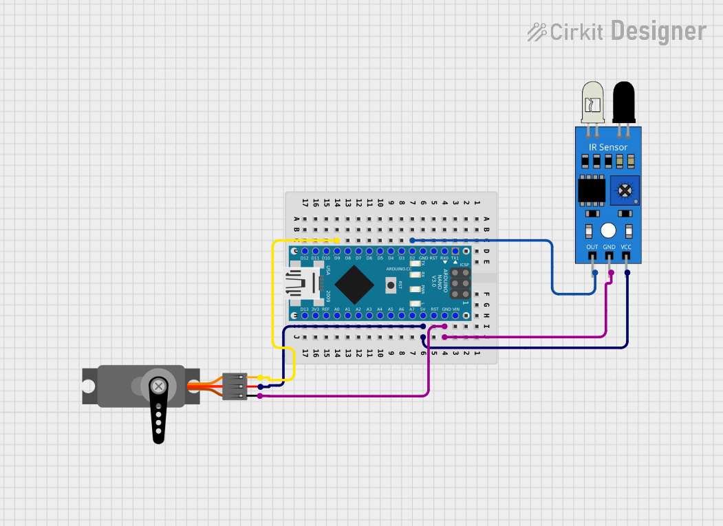
Circuit Documentation
Summary of the Circuit
This circuit consists of an Arduino Nano microcontroller, an infrared (IR) sensor, and a servo motor. The Arduino Nano serves as the central processing unit, controlling the servo motor based on the input from the IR sensor. The IR sensor detects the presence of objects or motion, and its output is read by the Arduino Nano. Depending on the sensor's output, the Arduino Nano sends a PWM (Pulse Width Modulation) signal to the servo motor to perform a specific action, such as rotating to a certain angle.
Component List
Arduino Nano
- Description: A compact microcontroller board based on the ATmega328P.
- Pins: D1/TX, D0/RX, RESET, GND, D2, D3, D4, D5, D6, D7, D8, D9, D10, D11/MOSI, D12/MISO, VIN, 5V, A7, A6, A5, A4, A3, A2, A1, A0, AREF, 3V3, D13/SCK.
IR Sensor
- Description: A sensor that detects infrared light to sense the presence or absence of objects.
- Pins: out, gnd, vcc.
Servo Motor
- Description: An actuator that can be precisely controlled for angular rotation.
- Pins: GND, VCC, PWM.
Wiring Details
Arduino Nano
- GND: Connected to the GND pins of the IR sensor and the servo motor.
- 5V: Powers the IR sensor and the servo motor by connecting to their VCC pins.
- D2: Reads the output from the IR sensor.
- D9: Sends PWM signal to control the servo motor.
IR Sensor
- out: Connected to the D2 pin on the Arduino Nano to send the detection signal.
- gnd: Connected to the GND pin on the Arduino Nano.
- vcc: Powered by the 5V pin on the Arduino Nano.
Servo Motor
- GND: Connected to the GND pin on the Arduino Nano.
- VCC: Powered by the 5V pin on the Arduino Nano.
- PWM: Receives PWM signal from the D9 pin on the Arduino Nano to control the motor's position.
Documented Code
Arduino Nano Code (sketch.ino)
void setup() {
  // put your setup code here, to run once:

}

void loop() {
  // put your main code here, to run repeatedly:

}
Note: The provided code is a template and does not contain any functional code to control the IR sensor or the servo motor. The user is expected to fill in the setup and loop functions with the necessary code to read the IR sensor output and control the servo motor accordingly.