Cirkit Designer
Your all-in-one circuit design IDE
Home /
Project Documentation
Arduino UNO-Based Sensor Monitoring System with IR and Hall Sensors
Circuit Documentation
Summary
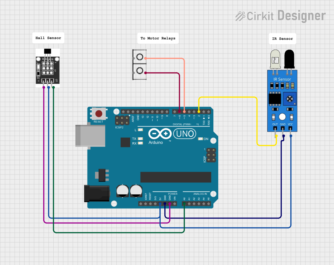
This document provides a detailed overview of a circuit involving an Arduino UNO, an IR sensor, a Hall sensor, and a wire connector. The circuit is designed to interface sensors with the Arduino for various input and output operations.
Component List
Arduino UNO
- Description: A microcontroller board based on the ATmega328P.
- Pins: UNUSED, IOREF, Reset, 3.3V, 5V, GND, Vin, A0, A1, A2, A3, A4, A5, SCL, SDA, AREF, D13, D12, D11, D10, D9, D8, D7, D6, D5, D4, D3, D2, D1, D0
IR Sensor
- Description: An infrared sensor used for detecting objects or measuring distance.
- Pins: out, gnd, vcc
Hall Sensor
- Description: A sensor used to detect the presence of a magnetic field.
- Pins: -, +, S
Wire Connector
- Description: A simple connector used to establish electrical connections.
- Pins: +, -
Comment
- Description: Placeholder for comments or notes in the circuit.
- Pins: None
Wiring Details
Arduino UNO
- 5V: Connected to the vcc pin of the IR sensor and the + pin of the Hall sensor.
- GND: Connected to the gnd pin of the IR sensor and the - pin of the Hall sensor.
- A0: Connected to the S pin of the Hall sensor.
- D6: Connected to the - pin of the wire connector.
- D5: Connected to the + pin of the wire connector.
- D2: Connected to the out pin of the IR sensor.
IR Sensor
- vcc: Connected to the 5V pin of the Arduino UNO.
- gnd: Connected to the GND pin of the Arduino UNO.
- out: Connected to the D2 pin of the Arduino UNO.
Hall Sensor
- +: Connected to the 5V pin of the Arduino UNO.
- -: Connected to the GND pin of the Arduino UNO.
- S: Connected to the A0 pin of the Arduino UNO.
Wire Connector
- +: Connected to the D5 pin of the Arduino UNO.
- -: Connected to the D6 pin of the Arduino UNO.
Documented Code
Arduino UNO Code (sketch.ino)
void setup() {
  // put your setup code here, to run once:

}

void loop() {
  // put your main code here, to run repeatedly:

}
Documentation (documentation.txt)
This document provides a comprehensive overview of the circuit, including the components used, their wiring details, and the code for the Arduino UNO.