Arduino Uno R3 and HMC5883L Compass Interface
Circuit Documentation
Summary of the Circuit
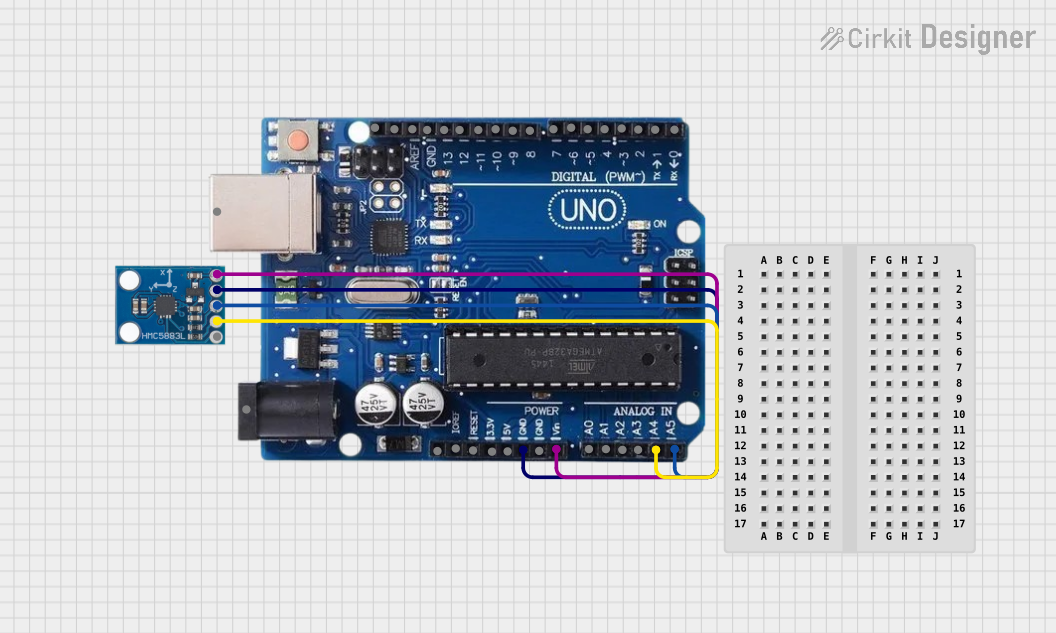
This circuit integrates an HMC5883L compass module with an Arduino Uno R3 microcontroller. The purpose of the circuit is to read magnetic field data from the HMC5883L compass and process this information with the Arduino Uno R3. The Arduino is programmed to communicate with the compass module via the I2C protocol, read the magnetometer data, and output the readings to the Serial Monitor. The compass module is powered directly from the Arduino's voltage input pin, and the ground is shared between the two devices to complete the circuit.
Component List
Arduino Uno R3
- Description: A microcontroller board based on the ATmega328P. It has 14 digital input/output pins, 6 analog inputs, a 16 MHz quartz crystal, a USB connection, a power jack, an ICSP header, and a reset button.
- Purpose: Acts as the central processing unit for the circuit, reading data from the HMC5883L compass and outputting the results.
HMC5883L Compass
- Description: A surface-mount, multi-chip module designed for low-field magnetic sensing with a digital interface for applications such as low-cost compassing and magnetometry.
- Purpose: Measures the magnetic field and provides data to the Arduino Uno R3 via the I2C interface.
Wiring Details
Arduino Uno R3
- A4/SDA: Connected to the SDA pin of the HMC5883L compass for I2C data communication.
- A5/SCL: Connected to the SCL pin of the HMC5883L compass for I2C clock signal.
- GND: Connected to the GND pin of the HMC5883L compass to provide a common ground reference.
- VIN: Connected to the VCC pin of the HMC5883L compass to supply power.
HMC5883L Compass
- SDA: Connected to the A4/SDA pin of the Arduino Uno R3 for I2C data communication.
- SCL: Connected to the A5/SCL pin of the Arduino Uno R3 for I2C clock signal.
- GND: Connected to the GND pin of the Arduino Uno R3 to provide a common ground reference.
- VCC: Connected to the VIN pin of the Arduino Uno R3 to receive power.
Documented Code
Arduino Uno R3 Code
/*
 * Arduino Sketch for interfacing with HMC5883L Magnetometer
 * This code reads the magnetometer data and outputs it to the Serial Monitor.
 * Connections:
 * - HMC5883L GND to Arduino GND
 * - HMC5883L VCC to Arduino VIN
 * - HMC5883L SCL to Arduino A5/SCL
 * - HMC5883L SDA to Arduino A4/SDA
 */

#include <Wire.h>

#define HMC5883L_ADDRESS 0x1E

void setup() {
  Serial.begin(9600); // Initialize serial communication
  Wire.begin(); // Initialize I2C communication
  initHMC5883L(); // Initialize HMC5883L sensor
}

void loop() {
  int16_t x, y, z;
  readHMC5883L(x, y, z); // Read magnetometer data
  Serial.print("X: "); Serial.print(x);
  Serial.print(" Y: "); Serial.print(y);
  Serial.print(" Z: "); Serial.println(z);
  delay(500); // Delay for readability
}

void initHMC5883L() {
  Wire.beginTransmission(HMC5883L_ADDRESS);
  Wire.write(0x00); // Select Configuration Register A
  Wire.write(0x70); // 8-average, 15 Hz default, normal measurement
  Wire.endTransmission();

  Wire.beginTransmission(HMC5883L_ADDRESS);
  Wire.write(0x01); // Select Configuration Register B
  Wire.write(0xA0); // Gain = 5
  Wire.endTransmission();

  Wire.beginTransmission(HMC5883L_ADDRESS);
  Wire.write(0x02); // Select mode register
  Wire.write(0x00); // Continuous measurement mode
  Wire.endTransmission();
}

void readHMC5883L(int16_t &x, int16_t &y, int16_t &z) {
  Wire.beginTransmission(HMC5883L_ADDRESS);
  Wire.write(0x03); // Select data register
  Wire.endTransmission();

  Wire.requestFrom(HMC5883L_ADDRESS, 6);
  if (Wire.available() == 6) {
    x = Wire.read() << 8 | Wire.read();
    z = Wire.read() << 8 | Wire.read();
    y = Wire.read() << 8 | Wire.read();
  }
}
This code initializes the HMC5883L magnetometer and reads the X, Y, and Z axis magnetometer data, which is then printed to the Serial Monitor. The initHMC5883L function configures the sensor with an 8-average, 15 Hz update rate, and normal measurement mode. The readHMC5883L function reads the data from the sensor and stores it in the provided variables.