
Circuit Documentation
Summary
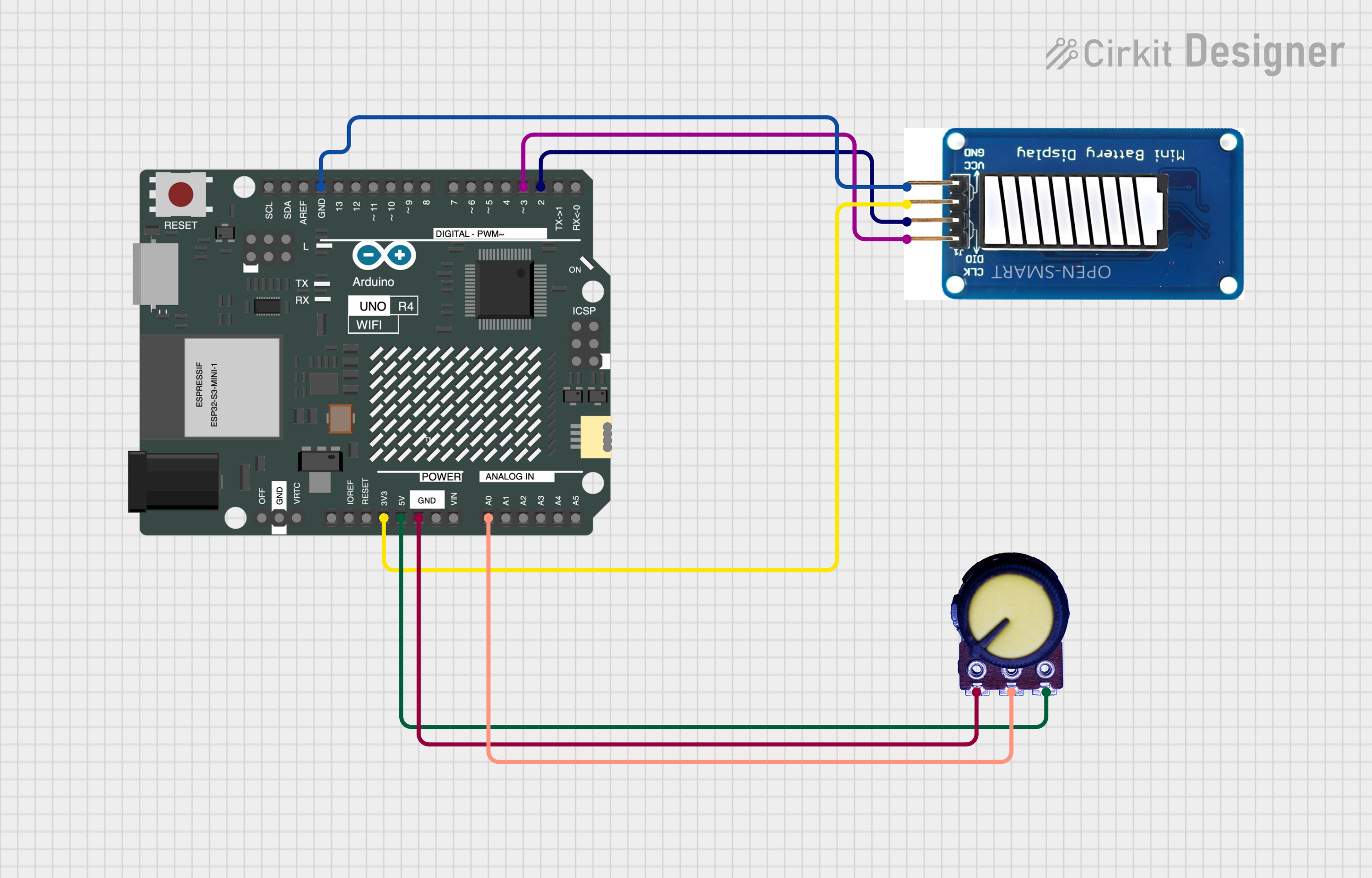
The circuit in question is designed to interface a TM1651 display driver with an Arduino UNO R4 WiFi microcontroller and a potentiometer. The TM1651 is used to display levels that correspond to the analog value read from the potentiometer. The Arduino UNO R4 WiFi is the central processing unit of the circuit, reading the potentiometer value, processing it, and then sending the appropriate commands to the TM1651 to update the display.
Component List
YY (TM1651 Display Driver)
- Pins: CLK, DIO, VCC, GND
- Description: A display driver used to control LED displays.
- Purpose: To display levels based on the potentiometer's analog input.
Arduino UNO R4 WiFi
- Pins: OFF, GND, VRTC, IIC0_SCL, IIC0_SDA, 3V3, GPIO 41, GPIO 0, GPIO 42, GPIO 43, GPIO 44, BOOT, IOREF, RESET, 5V, VIN, A0, A1, A2, A3, A4, A5, RSPCKA, CIPO, COPI, D0/RX, D1/TX, D2, D3, D4, D5, D6, D7, D8, D9, D10, D11, D12, D13, AREF, SDA, SCL
- Description: A microcontroller board based on the ATmega328P with WiFi capabilities.
- Purpose: To read the analog input from the potentiometer and control the TM1651 display driver.
Potentiometer
- Pins: GND, Output, VCC
- Description: A variable resistor with three terminals.
- Purpose: To provide a variable voltage that can be read by the Arduino as an analog input.
Wiring Details
YY (TM1651 Display Driver)
- CLK: Connected to Arduino's D3 pin.
- DIO: Connected to Arduino's D2 pin.
- VCC: Connected to Arduino's 3V3 pin.
- GND: Connected to Arduino's GND pin.
Arduino UNO R4 WiFi
- D3: Connected to TM1651's CLK pin.
- D2: Connected to TM1651's DIO pin.
- 3V3: Provides power to TM1651's VCC pin.
- GND: Common ground for TM1651 and Potentiometer.
- 5V: Provides power to Potentiometer's VCC pin.
- A0: Reads the analog voltage from Potentiometer's Output pin.
Potentiometer
- VCC: Connected to Arduino's 5V pin.
- Output: Connected to Arduino's A0 pin.
- GND: Connected to Arduino's GND pin.
Documented Code
#include "TM1651.h"

#define CLK 3       // TM1651's CLK pin
#define DIO 2       // TM1651's DIO pin
#define POT_PIN A0  // Potentiometer's analog pin

TM1651 batteryDisplay(CLK, DIO);

void setup() {
  batteryDisplay.init();               // Initialize TM1651
  batteryDisplay.set(BRIGHTEST);       // Set display brightness
}

void loop() {
  int potValue = analogRead(POT_PIN);  // Read the potentiometer value (0-1023)

  // Convert the potentiometer value from 0-1023 to a level from 0-7
  int displayLevel = map(potValue, 0, 1023, 0, 7);

  // Display the converted level on the TM1651
  batteryDisplay.displayLevel(displayLevel);

  delay(100);  // Delay for update interval
}
The code is written for the Arduino UNO R4 WiFi and is responsible for initializing the TM1651 display driver, reading the analog value from the potentiometer, converting this value to a display level, and updating the TM1651 display accordingly. The delay(100) function call ensures that the display updates at a reasonable interval.