
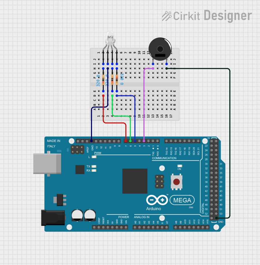
Circuit Documentation
Summary of the Circuit
This circuit is designed around the Arduino Mega 2560 microcontroller, which serves as the central processing unit for controlling various peripherals including a multi-color LED (common cathode type) and a piezo buzzer. The LED's anodes are connected through individual resistors to the PWM-capable digital pins of the Arduino, allowing for color mixing through pulse-width modulation. The piezo buzzer is connected to another PWM-capable pin for sound generation. Ground connections are shared between the Arduino, the LED, and the buzzer, establishing a common reference point for the circuit.
Component List
Arduino Mega 2560
- Description: A microcontroller board based on the ATmega2560, with a wide range of digital and analog I/O pins.
- Purpose: Acts as the main controller for the circuit, driving the LED and buzzer.
LED: Four Pin (Common Cathode)
- Description: A multi-color LED with separate pins for the red, green, and blue anodes and a common cathode.
- Purpose: Provides visual output in various colors by mixing red, green, and blue.
Piezo Buzzer
- Description: An electronic device that emits sound when an electrical signal is applied.
- Purpose: Generates audio signals or beeps when activated by the Arduino.
Resistor (320 Ohms)
- Description: A passive two-terminal electrical component that implements electrical resistance as a circuit element.
- Purpose: Limits the current flowing through the LED to prevent damage.
Wiring Details
Arduino Mega 2560
- Digital Pin D7 (PWM): Connected to a 320 Ohm resistor, which is then connected to the red anode of the LED.
- Digital Pin D6 (PWM): Connected to a 320 Ohm resistor, which is then connected to the green anode of the LED.
- Digital Pin D5 (PWM): Connected to a 320 Ohm resistor, which is then connected to the blue anode of the LED.
- Digital Pin D3 (PWM): Connected to pin 1 of the Piezo Buzzer.
- Ground (GND): Connected to the common cathode of the LED and pin 2 of the Piezo Buzzer.
LED: Four Pin (Common Cathode)
- Red Anode: Connected to a 320 Ohm resistor, which is then connected to Arduino's D7 (PWM).
- Green Anode: Connected to a 320 Ohm resistor, which is then connected to Arduino's D6 (PWM).
- Blue Anode: Connected to a 320 Ohm resistor, which is then connected to Arduino's D5 (PWM).
- Common Cathode: Connected to the Arduino's Ground (GND).
Piezo Buzzer
- Pin 1: Connected to Arduino's D3 (PWM).
- Pin 2: Connected to the Arduino's Ground (GND).
Resistor (320 Ohms)
- One pin: Connected to the corresponding anode of the LED (red, green, or blue).
- Other pin: Connected to the corresponding PWM pin on the Arduino (D7, D6, or D5).
Documented Code
Arduino Mega 2560 - sketch.ino
void setup() {
  // put your setup code here, to run once:

}

void loop() {
  // put your main code here, to run repeatedly:

}
Arduino Mega 2560 - documentation.txt
(No additional documentation provided)
This concludes the documentation for the provided circuit. The code provided is a template and does not contain any functional implementation. To control the LED and buzzer, the user must implement the setup and loop functions with the appropriate logic.