ESP32-Based Environmental Monitoring System with Vibration and Sound Detection
Circuit Documentation
Summary
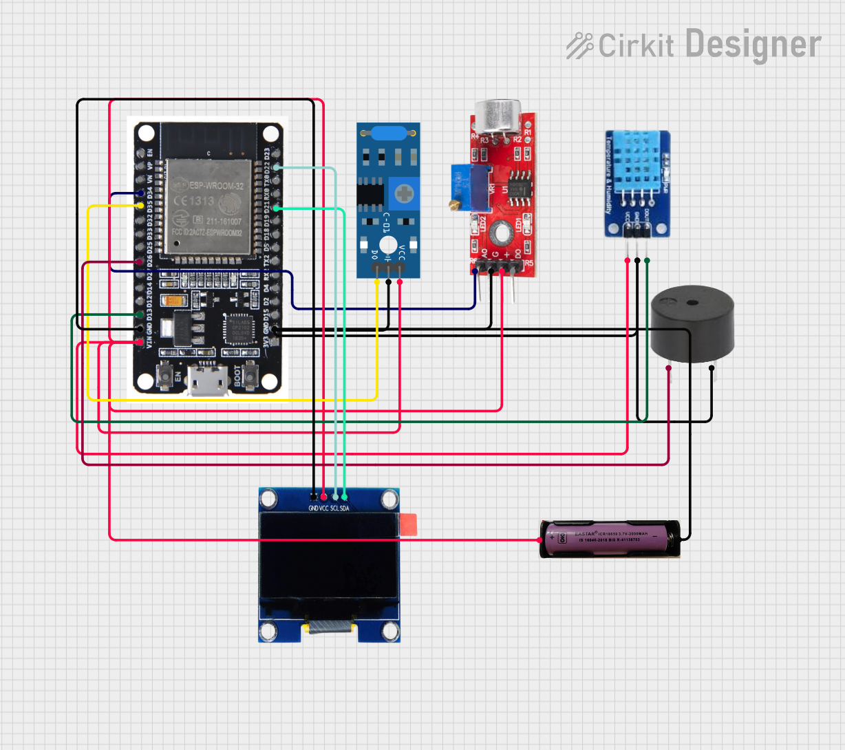
The circuit in question is designed to interface various sensors and output devices with an ESP32 microcontroller. The ESP32 serves as the central processing unit, reading sensor data, controlling a buzzer, and displaying information on an OLED display. The sensors include a SW-420 Vibration Sensor and a Sound Sensor for detecting physical and sound changes in the environment, respectively. A DHT11 sensor is used for measuring temperature and humidity. The OLED display provides a user interface for data visualization. A buzzer is included for audible alerts. The circuit is powered by a 3.7V power source.
Component List
ESP32
- Microcontroller with WiFi and Bluetooth capabilities.
- It has a variety of digital and analog pins for interfacing with peripherals.
SW-420 Vibration Sensor
- Detects vibrations and outputs a digital signal.
Sound Sensor
- Detects sound levels and provides both analog and digital outputs.
DHT11
- A sensor for measuring temperature and humidity, providing a digital output.
Buzzer
- An audible signaling device that can be controlled digitally.
OLED 1.3" Display
- A small display for showing text and graphics, interfaced via I2C.
3.7V Power Source
- Provides power to the circuit.
Wiring Details
ESP32
D34connected to Sound Sensor Analog output.D35connected to SW-420 Vibration Sensor Digital output.D26connected to Buzzer PIN.D13connected to DHT11 DATA.GNDconnected to common ground.VINconnected to 3.7V power source.D21(SDA) andD22(SCL) connected to OLED 1.3" Display for I2C communication.
SW-420 Vibration Sensor
vccconnected to 3.7V power source.Groundconnected to common ground.Digital outputconnected to ESP32D35.
Sound Sensor
Analogconnected to ESP32D34.GNDconnected to common ground.VCCconnected to 3.7V power source.
DHT11
DATAconnected to ESP32D13.GNDconnected to common ground.VCCconnected to 3.7V power source.
Buzzer
PINconnected to ESP32D26.GNDconnected to common ground.
OLED 1.3" Display
GNDconnected to common ground.VCCconnected to 3.7V power source.SCLconnected to ESP32D22.SDAconnected to ESP32D21.
3.7V Power Source
+connected toVINon ESP32 andVCCon all other components.-connected to common ground.
Documented Code
No code has been provided for the microcontroller. The documentation of the code would typically include descriptions of the functions, initialization routines, main loop, and any interrupt service routines. It would also detail how the microcontroller interacts with each sensor and output device, including data acquisition, processing, and response actions.