
ESP32-CAM and SIM800L Wi-Fi Controlled Smart Relay with DC Motor
View and Edit Project In Cirkit Designer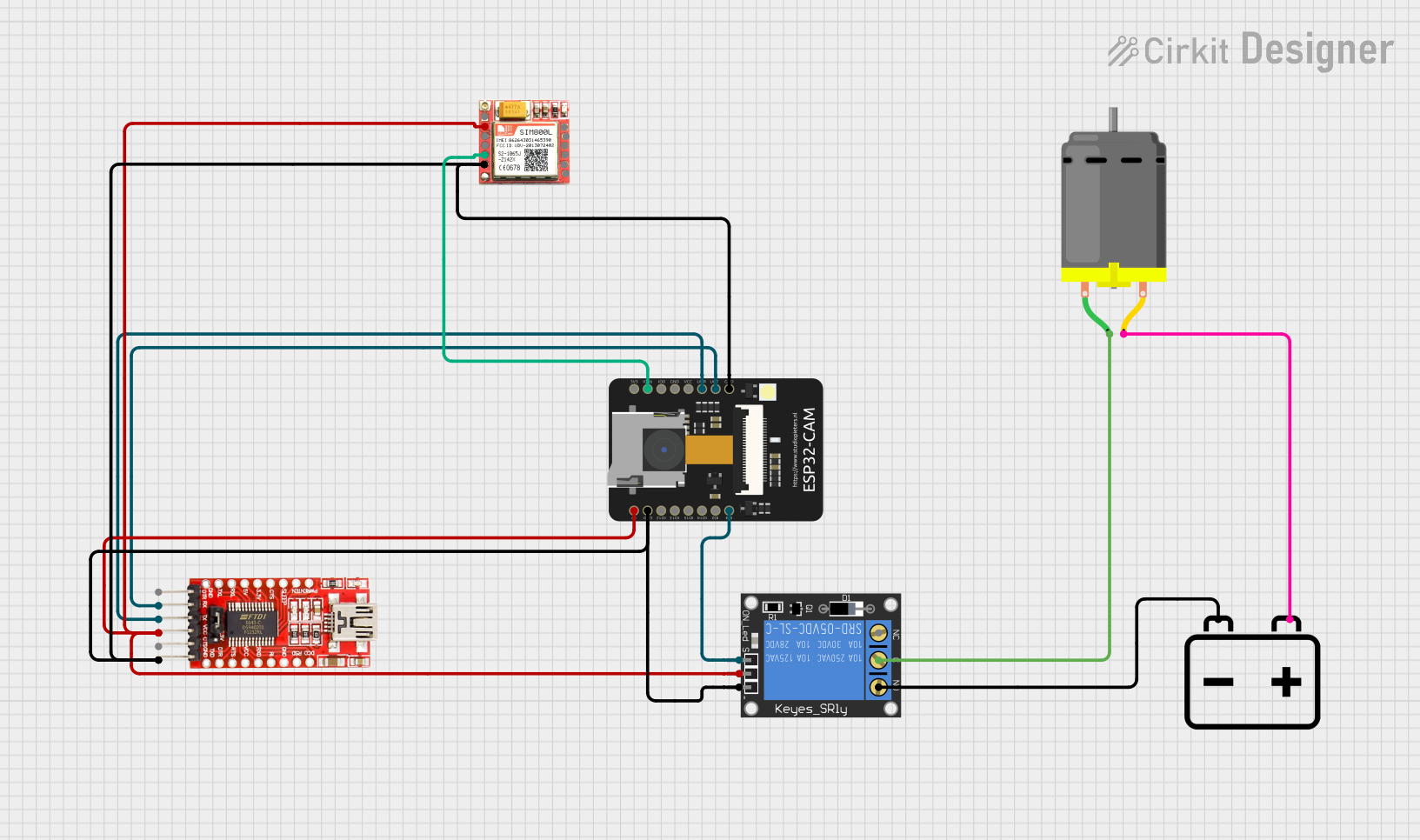
Circuit Documentation
Summary
This circuit involves a 1-Channel Relay, a 12V Battery, a DC Motor, a SIM 800L module, an ESP32-CAM, and an FTDI Programmer. The ESP32-CAM controls the relay, which in turn controls the DC motor. The SIM 800L module is used for communication, and the FTDI Programmer is used for programming the ESP32-CAM.
Component List
1-Channel Relay (5V 10A)
- Description: A relay module that allows a low-power microcontroller to control a high-power device.
- Pins: NC, signal, C, power, NO, ground
12V Battery
- Description: A power source providing 12V.
- Pins: -, +
DC Motor
- Description: A motor that runs on DC power.
- Pins: pin 1, pin 2
SIM 800L
- Description: A GSM/GPRS module for communication.
- Pins: NFT, RING, VCC, DTR, RST, MIC +, RXD, MIC-, TXD, SPK+, GND, SPK-
ESP32-CAM
- Description: A microcontroller with a built-in camera and WiFi capabilities.
- Pins: 5V, GND, IO12, IO13, IO15, IO14, IO2, IO4, VOT, VOR, VCC, IO0, IO16, 3V3
FTDI Programmer
- Description: A USB-to-serial converter used for programming microcontrollers.
- Pins: DTR, RX, TX, VCC, CTS, GND
Wiring Details
1-Channel Relay (5V 10A)
power is connected to:
- SIM 800L (VCC)
- FTDI Programmer (VCC)
- ESP32-CAM (5V)
ground is connected to:
- SIM 800L (GND)
- FTDI Programmer (GND)
- ESP32-CAM (GND)
signal is connected to:
- ESP32-CAM (IO4)
C is connected to:
- DC Motor (pin 1)
NO is connected to:
- 12V Battery (-)
12V Battery
- is connected to:
- 1-Channel Relay (NO)
+ is connected to:
- DC Motor (pin 2)
DC Motor
pin 1 is connected to:
- 1-Channel Relay (C)
pin 2 is connected to:
- 12V Battery (+)
SIM 800L
VCC is connected to:
- 1-Channel Relay (power)
- FTDI Programmer (VCC)
- ESP32-CAM (5V)
GND is connected to:
- 1-Channel Relay (ground)
- FTDI Programmer (GND)
- ESP32-CAM (GND)
TXD is connected to:
- ESP32-CAM (IO16)
ESP32-CAM
5V is connected to:
- 1-Channel Relay (power)
- SIM 800L (VCC)
- FTDI Programmer (VCC)
GND is connected to:
- 1-Channel Relay (ground)
- SIM 800L (GND)
- FTDI Programmer (GND)
IO4 is connected to:
- 1-Channel Relay (signal)
IO16 is connected to:
- SIM 800L (TXD)
VOT is connected to:
- FTDI Programmer (RX)
VOR is connected to:
- FTDI Programmer (TX)
FTDI Programmer
VCC is connected to:
- 1-Channel Relay (power)
- SIM 800L (VCC)
- ESP32-CAM (5V)
GND is connected to:
- 1-Channel Relay (ground)
- SIM 800L (GND)
- ESP32-CAM (GND)
RX is connected to:
- ESP32-CAM (VOT)
TX is connected to:
- ESP32-CAM (VOR)
Documented Code
SIM 800L Code
void setup() {
  // put your setup code here, to run once:

}

void loop() {
  // put your main code here, to run repeatedly:

}
ESP32-CAM Code
#include "esp_camera.h"
#include <WiFi.h>
//
// WARNING!!! Make sure that you have either selected ESP32 Wrover Module,
//            or another board which has PSRAM enabled
//
// Select camera model
//#define CAMERA_MODEL_WROVER_KIT
//#define CAMERA_MODEL_ESP_EYE
//#define CAMERA_MODEL_M5STACK_PSRAM
//#define CAMERA_MODEL_M5STACK_WIDE
#define CAMERA_MODEL_AI_THINKER
#include "camera_pins.h"
const char* ssid = "Galaxy-M20";
const char* password = "ac312124";
#define LED_BUILTIN 4
#define relay 4
#define buzzer 2
boolean matchFace = false;
boolean activeRelay = false;
long prevMillis = 0;
int interval = 5000;
void startCameraServer();
void setup() {
  Serial.begin(115200);
  Serial.setDebugOutput(true);
  Serial.println();
  pinMode(relay, OUTPUT);
  pinMode(buzzer, OUTPUT);
  pinMode (LED_BUILTIN, OUTPUT);
  digitalWrite(LED_BUILTIN, LOW);
  digitalWrite(relay, LOW);
  digitalWrite(buzzer, LOW);
  camera_config_t config;
  config.ledc_channel = LEDC_CHANNEL_0;
  config.ledc_timer = LEDC_TIMER_0;
  config.pin_d0 = Y2_GPIO_NUM;
  config.pin_d1 = Y3_GPIO_NUM;
  config.pin_d2 = Y4_GPIO_NUM;
  config.pin_d3 = Y5_GPIO_NUM;
  config.pin_d4 = Y6_GPIO_NUM;
  config.pin_d5 = Y7_GPIO_NUM;
  config.pin_d6 = Y8_GPIO_NUM;
  config.pin_d7 = Y9_GPIO_NUM;
  config.pin_xclk = XCLK_GPIO_NUM;
  config.pin_pclk = PCLK_GPIO_NUM;
  config.pin_vsync = VSYNC_GPIO_NUM;
  config.pin_href = HREF_GPIO_NUM;
  config.pin_sscb_sda = SIOD_GPIO_NUM;
  config.pin_sscb_scl = SIOC_GPIO_NUM;
  config.pin_pwdn = PWDN_GPIO_NUM;
  config.pin_reset = RESET_GPIO_NUM;
  config.xclk_freq_hz = 20000000;
  config.pixel_format = PIXFORMAT_JPEG;
  //init with high specs to pre-allocate larger buffers
  if(psramFound()){
    config.frame_size = FRAMESIZE_UXGA;
    config.jpeg_quality = 10;
    config.fb_count = 2;
  } else {
    config.frame_size = FRAMESIZE_SVGA;
    config.jpeg_quality = 12;
    config.fb_count = 1;
  }
#if defined(CAMERA_MODEL_ESP_EYE)
  pinMode(13, INPUT_PULLUP);
  pinMode(14, INPUT_PULLUP);
#endif
  // camera init
  esp_err_t err = esp_camera_init(&config);
  if (err != ESP_OK) {
    Serial.printf("Camera init failed with error 0x%x", err);
    return;
  }
  sensor_t * s = esp_camera_sensor_get();
  //initial sensors are flipped vertically and colors are a bit saturated
  if (s->id.PID == OV3660_PID) {
    s->set_vflip(s, 1);//flip it back
    s->set_brightness(s, 1);//up the blightness just a bit
    s->set_saturation(s, -2);//lower the saturation
  }
  //drop down frame size for higher initial frame rate
  s->set_framesize(s, FRAMESIZE_QVGA);
#if defined(CAMERA_MODEL_M5STACK_WIDE)
  s->set_vflip(s, 1);
  s->set_hmirror(s, 1);
#endif
  WiFi.begin(ssid, password);
  while (WiFi.status() != WL_CONNECTED) {
    delay(500);
    Serial.print(".");
  }
  Serial.println("");
  Serial.println("WiFi connected");
  startCameraServer();
  Serial.print("Camera Ready! Use 'http://");
  Serial.print(WiFi.localIP());
  Serial.println("' to connect");
}
void loop() {
    if (matchFace == true && activeRelay == false){
      activeRelay = true;
      digitalWrite (relay, HIGH);
      digitalWrite (buzzer, HIGH);
      delay(800);
      digitalWrite (buzzer, LOW);
      prevMillis = millis();
    }
    if(activeRelay == true && millis()- prevMillis > interval){
      activeRelay = false;
      matchFace = false;
      digitalWrite(relay, LOW);
    }
}