ESP32-Controlled GPS and Metal Detector Robot with L298N Motor Driver
Circuit Documentation
Summary
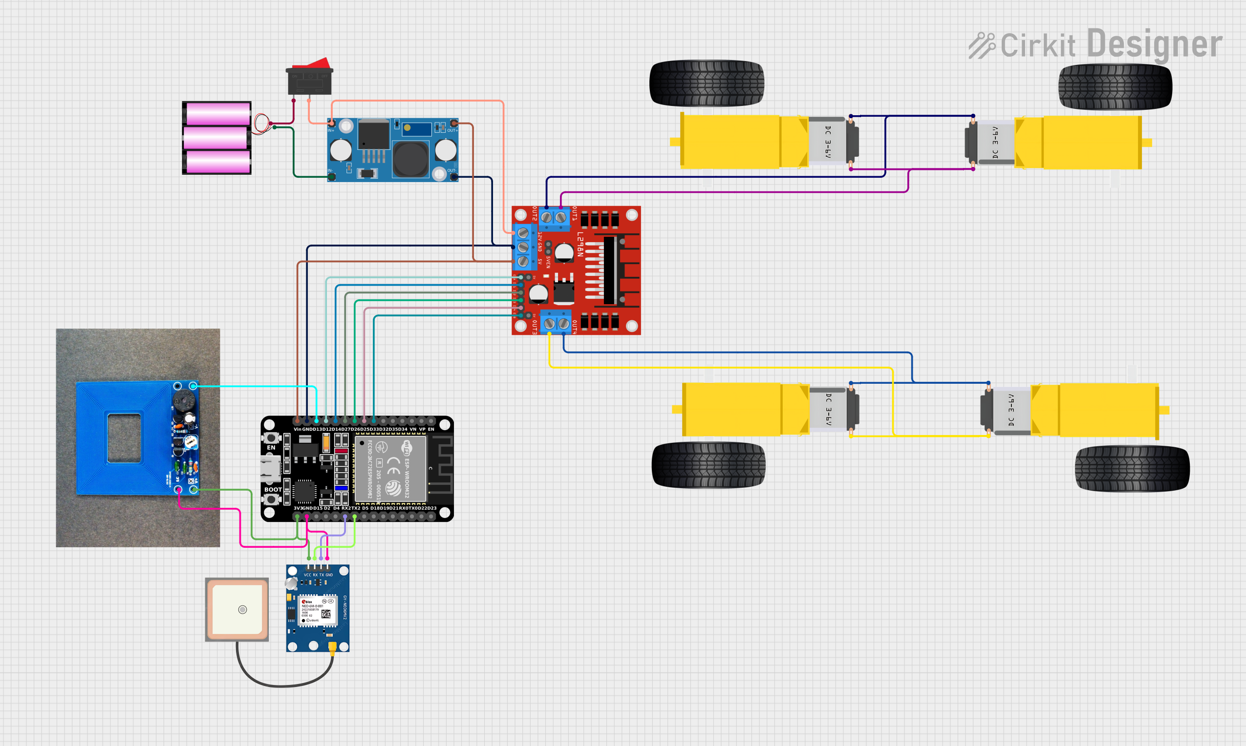
The circuit in question appears to be designed for a mobile platform, possibly a robot, which includes an ESP32 microcontroller for processing and control, a GPS module for positioning, a metal detector for object detection, motor drivers for actuating wheels, and a power management system. The ESP32 is interfaced with a GPS NEO 6M module for location tracking and a metal detector for detecting metallic objects. The L298N motor driver is used to control the gearmotors attached to the wheels, allowing for movement. The power management system consists of a 12V battery, a step-down module to regulate voltage, and a rocker switch for power control.
Component List
ESP32 (30 pin)
- Microcontroller with WiFi and Bluetooth capabilities.
- 30 GPIO pins including analog inputs, digital IOs, power, and ground.
GPS NEO 6M
- GPS module for receiving satellite positioning data.
- Pins: VCC, RX, TX, GND.
Gearmotor DC Wheels (Right and Left)
- DC motors with gear reduction used for driving wheels.
- Pins: PIN1, PIN2.
Battery 12V
- Power source for the circuit.
- Pins: + (positive), - (negative).
LM2596 Step Down Module
- Voltage regulator to step down the voltage from the battery.
- Pins: OUT-, OUT+, IN-, IN+.
Rocker Switch
- Mechanical switch to control the power flow in the circuit.
- Pins: 1, 2.
L298N DC Motor Driver
- Dual H-bridge motor driver for controlling the speed and direction of two DC motors.
- Multiple control and power pins including OUT1, OUT2, OUT3, OUT4, ENA, ENB, and others.
Metal Detector
- Sensor for detecting metallic objects.
- Pins: VCC, GND, D (digital output).
Wiring Details
ESP32 (30 pin)
- D33 connected to L298N DC motor driver ENB.
- D25 connected to L298N DC motor driver IN4.
- D26 connected to L298N DC motor driver IN3.
- D27 connected to L298N DC motor driver IN2.
- D14 connected to L298N DC motor driver IN1.
- D12 connected to L298N DC motor driver ENA.
- D13 connected to Metal detector D.
- GND connected to L298N DC motor driver GND, LM2596 Step Down Module OUT-, GPS NEO 6M GND, and Metal detector GND.
- Vin connected to L298N DC motor driver 5V and LM2596 Step Down Module OUT+.
- TX2 connected to GPS NEO 6M RX.
- RX2 connected to GPS NEO 6M TX.
- 3V3 connected to GPS NEO 6M VCC and Metal detector VCC.
GPS NEO 6M
- RX connected to ESP32 TX2.
- TX connected to ESP32 RX2.
- GND connected to ESP32 GND.
- VCC connected to ESP32 3V3.
Gearmotor DC Wheels (Right and Left)
- Right and Left motors connected to L298N DC motor driver OUT1, OUT2, OUT3, and OUT4 in a cross-configuration for differential drive.
Battery 12V
- connected to Rocker Switch 1.
- connected to LM2596 Step Down Module IN-.
LM2596 Step Down Module
- OUT- connected to ESP32 GND and L298N DC motor driver GND.
- OUT+ connected to ESP32 Vin and L298N DC motor driver 5V.
- IN- connected to Battery 12V -.
- IN+ connected to Rocker Switch 2.
Rocker Switch
- 1 connected to Battery 12V +.
- 2 connected to LM2596 Step Down Module IN+ and L298N DC motor driver 12V.
L298N DC Motor Driver
- ENA, ENB connected to ESP32 for speed control.
- IN1, IN2, IN3, IN4 connected to ESP32 for direction control.
- OUT1, OUT2, OUT3, OUT4 connected to Gearmotor DC Wheels.
- 5V connected to ESP32 Vin.
- GND connected to ESP32 GND.
- 12V connected to Rocker Switch 2.
Metal Detector
- D connected to ESP32 D13.
- GND connected to ESP32 GND.
- VCC connected to ESP32 3V3.
Documented Code
No code was provided for the microcontroller. However, the expected code would handle the following tasks:
- Initialize and configure the ESP32 GPIO pins for communication with the GPS module, metal detector, and motor driver.
- Read data from the GPS module and metal detector.
- Control the motor driver to actuate the gearmotors based on sensor inputs and possibly remote commands.
- Implement power management routines to handle the on/off state through the rocker switch.
For further development, code should be written and documented to fulfill the above functionalities.