
Wi-Fi Controlled Smart Lighting System with ESP32 and Relay Module
View and Edit Project In Cirkit Designer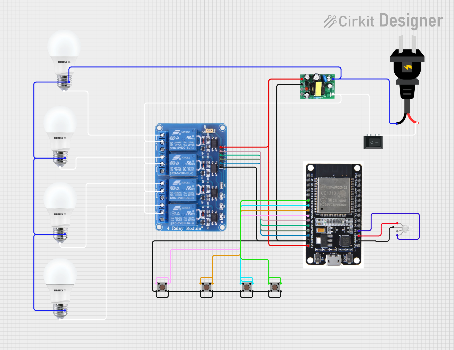
Circuit Documentation
Summary
This circuit involves an ESP32 microcontroller controlling a 4-channel relay module, which in turn controls four bulbs. The circuit also includes an AC-DC power supply unit, a rocker switch, pushbuttons, and an RGB LED. The ESP32 is programmed to control the relays and read the state of the pushbuttons. The relays are used to switch the bulbs on and off. The RGB LED is used for visual feedback.
Component List
Relay 4 Channel 5V
- Description: A relay module with four channels, each capable of switching high voltage devices.
- Pins: GND, IN1, IN2, IN3, IN4, VCC, COM1, COM2, COM3, COM4, NO1, NO2, NO3, NO4, NC1, NC2, NC3, NC4
ESP32
- Description: A powerful microcontroller with Wi-Fi and Bluetooth capabilities.
- Pins: EN, VP, VN, D34, D35, D32, D33, D25, D26, D27, D14, D12, D13, GND, VIN, 3V3, D15, D2, D4, RX2, TX2, D5, D18, D19, D21, RX0, TX0, D22, D23, BOOT
BULB
- Description: Standard light bulbs.
- Pins: +, -
AC Source
- Description: Provides AC power to the circuit.
- Pins: +, -
AC-DC PSU Board 220V-5V&12V
- Description: Converts AC power to 5V and 12V DC power.
- Pins: AC-N, AC-L, +5V, GND, +12V
Rocker Switch (SPST)
- Description: A single-pole single-throw switch.
- Pins: 1, 2
RGB LED (Wokwi compatible)
- Description: An RGB LED for visual feedback.
- Pins: R, COM, G, B
Pushbutton
- Description: Standard pushbuttons.
- Pins: Pin 3 (out), Pin 4 (out), Pin 1 (in), Pin 2 (in)
Wiring Details
Relay 4 Channel 5V
- GND: Connected to GND of ESP32, AC-DC PSU board, and all pushbuttons.
- IN1: Connected to D13 of ESP32.
- IN2: Connected to D12 of ESP32.
- IN3: Connected to D14 of ESP32.
- IN4: Connected to D27 of ESP32.
- VCC: Connected to VIN of ESP32 and +5V of AC-DC PSU board.
- COM1, COM2, COM3, COM4: Connected to AC-L of AC-DC PSU board and pin 1 of Rocker Switch.
- NO1: Connected to + of BULB 1.
- NO2: Connected to + of BULB 2.
- NO3: Connected to + of BULB 3.
- NO4: Connected to + of BULB 4.
- NC1, NC2, NC3, NC4: Not connected.
ESP32
- GND: Connected to GND of Relay 4 Channel 5V, AC-DC PSU board, and all pushbuttons.
- D13: Connected to IN1 of Relay 4 Channel 5V.
- D12: Connected to IN2 of Relay 4 Channel 5V.
- D14: Connected to IN3 of Relay 4 Channel 5V.
- D27: Connected to IN4 of Relay 4 Channel 5V.
- VIN: Connected to VCC of Relay 4 Channel 5V and +5V of AC-DC PSU board.
- D32: Connected to Pin 3 and Pin 4 of Pushbutton 1.
- D33: Connected to Pin 3 and Pin 4 of Pushbutton 2.
- D25: Connected to Pin 3 and Pin 4 of Pushbutton 3.
- D26: Connected to Pin 3 and Pin 4 of Pushbutton 4.
- GND: Connected to COM of RGB LED.
- D15: Connected to R of RGB LED.
- D2: Connected to B of RGB LED.
BULB
- +: Connected to NO1, NO2, NO3, and NO4 of Relay 4 Channel 5V.
- -: Connected to - of AC Source and AC-N of AC-DC PSU board.
AC Source
- +: Connected to pin 2 of Rocker Switch.
- -: Connected to - of all bulbs and AC-N of AC-DC PSU board.
AC-DC PSU Board 220V-5V&12V
- AC-N: Connected to - of AC Source and - of all bulbs.
- AC-L: Connected to COM1, COM2, COM3, COM4 of Relay 4 Channel 5V and pin 1 of Rocker Switch.
- +5V: Connected to VCC of Relay 4 Channel 5V and VIN of ESP32.
- GND: Connected to GND of ESP32, Relay 4 Channel 5V, and all pushbuttons.
Rocker Switch (SPST)
- 1: Connected to AC-L of AC-DC PSU board and COM1, COM2, COM3, COM4 of Relay 4 Channel 5V.
- 2: Connected to + of AC Source.
RGB LED (Wokwi compatible)
- R: Connected to D15 of ESP32.
- COM: Connected to GND of ESP32.
- G: Not connected.
- B: Connected to D2 of ESP32.
Pushbutton
- Pin 1 (in): Connected to GND.
- Pin 2 (in): Connected to GND.
- Pin 3 (out): Connected to D32, D33, D25, and D26 of ESP32.
- Pin 4 (out): Connected to D32, D33, D25, and D26 of ESP32.
Code
No code provided.