
Arduino Mega 2560 Controlled RGB Panel Display with Bluetooth Connectivity and SD Card Logging
View and Edit Project In Cirkit Designer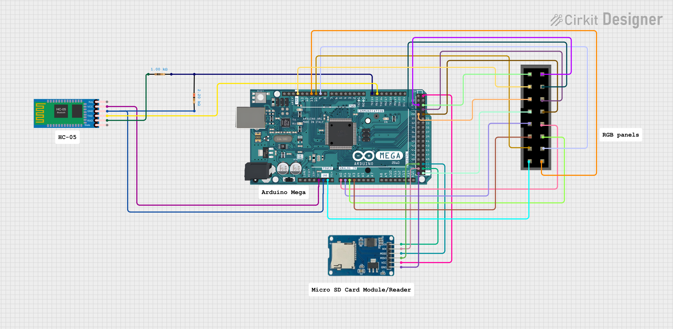
Circuit Documentation
Summary of the Circuit
This circuit is designed to interface an Arduino Mega 2560 with an HC-05 Bluetooth Module, a Micro SD Card Module, and RGB panels. The Arduino Mega 2560 serves as the central processing unit, controlling the data flow between the Bluetooth module, the SD card module, and the RGB panels. The HC-05 Bluetooth Module allows for wireless communication, while the Micro SD Card Module provides storage capabilities. The RGB panels are used for display purposes. The circuit includes resistors for current limiting and voltage level matching.
Component List
Arduino Mega 2560
- Description: A microcontroller board based on the ATmega2560.
- Pins: Multiple digital and analog I/O pins, power supply pins, and communication interface pins.
HC-05 Bluetooth Module
- Description: A wireless communication module that allows for Bluetooth connectivity.
- Pins: Key, VCC, TXD, RXD, State, GND.
Resistor (2.2k Ohms)
- Description: A passive two-terminal electrical component that implements electrical resistance as a circuit element.
- Resistance: 2200 Ohms.
Resistor (1k Ohms)
- Description: Another resistor with a lower resistance value.
- Resistance: 1000 Ohms.
Micro SD Card Module
- Description: A module that allows micro SD cards to be read from and written to by the microcontroller.
- Pins: cs, sck, mosi, miso, vcc, gnd.
RGB Panels
- Description: Panels consisting of RGB LEDs that can display a variety of colors.
- Pins: Multiple pins for controlling individual colors and power.
Comments
- Description: Components labeled as "Comment" are likely placeholders or notes within the circuit design and do not represent physical components.
Wiring Details
Arduino Mega 2560
- 5V connected to HC-05 Bluetooth Module VCC and Micro SD Card Module vcc.
- GND connected to HC-05 Bluetooth Module GND, Micro SD Card Module gnd, RGB panels pin 15, and one side of both resistors.
- A0 to A3 connected to RGB panels pins 10, 9, 12, and 11 respectively.
- D15/RX3 connected to HC-05 Bluetooth Module TXD.
- D14/TX3 connected through a 1k Ohm resistor to HC-05 Bluetooth Module RXD.
- D9 PWM to D11 PWM connected to RGB panels pins 14, 13, and 16 respectively.
- D52, D50, D53, and D51 connected to Micro SD Card Module sck, miso, cs, and mosi respectively.
- D28 to D25 connected to RGB panels pins 5, 4, 2, and 1 respectively.
- D29, D27, and D26 connected to RGB panels pins 8, 6, and 4 respectively.
HC-05 Bluetooth Module
- VCC connected to Arduino Mega 2560 5V.
- GND connected to Arduino Mega 2560 GND.
- TXD connected to Arduino Mega 2560 D15/RX3.
- RXD connected through a 1k Ohm resistor to Arduino Mega 2560 D14/TX3.
Resistor (2.2k Ohms)
- One side connected to Arduino Mega 2560 GND.
Resistor (1k Ohms)
- One side connected to Arduino Mega 2560 D14/TX3.
- The other side connected to HC-05 Bluetooth Module RXD.
Micro SD Card Module
- cs connected to Arduino Mega 2560 D53.
- sck connected to Arduino Mega 2560 D52.
- mosi connected to Arduino Mega 2560 D51.
- miso connected to Arduino Mega 2560 D50.
- vcc connected to Arduino Mega 2560 5V.
- gnd connected to Arduino Mega 2560 GND.
RGB Panels
- Various control pins connected to Arduino Mega 2560 analog and digital pins as specified in the wiring details.
- GND connected to Arduino Mega 2560 GND.
Documented Code
Arduino Mega 2560 Code (sketch.ino)
void setup() {
  // put your setup code here, to run once:

}

void loop() {
  // put your main code here, to run repeatedly:

}
Additional Notes
- The provided code is a template and does not contain any functional code for the operation of the circuit components.
- Further implementation is required to control the RGB panels, manage Bluetooth communication, and interact with the Micro SD Card Module.
- The code should be expanded to initialize the communication interfaces (e.g., SPI for the SD card and serial for Bluetooth), configure the I/O pins, and implement the desired functionality.