
Circuit Documentation
Summary
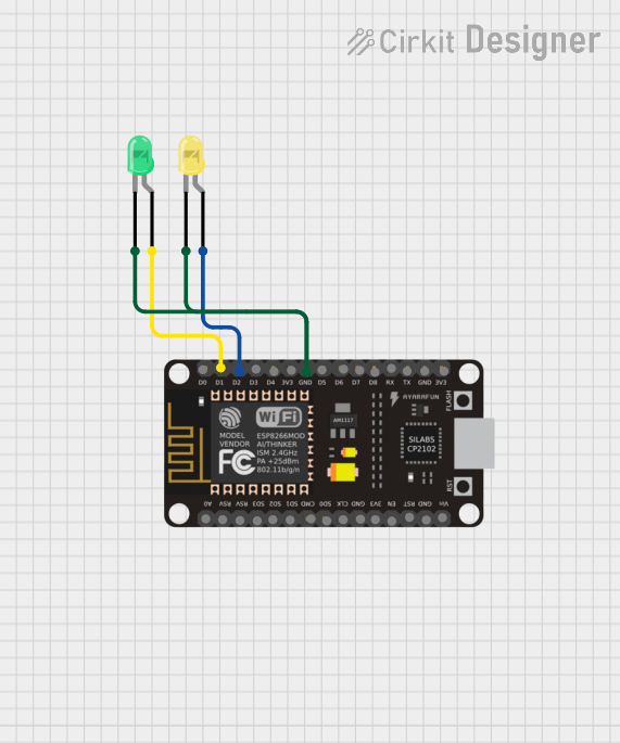
This document provides a detailed overview of a simple circuit involving an ESP8266 NodeMCU microcontroller and two LEDs (one yellow and one green). The ESP8266 NodeMCU controls the LEDs, with the green LED connected to pin D1 and the yellow LED connected to pin D2. Both LEDs share a common ground connection with the ESP8266 NodeMCU.
Component List
ESP8266 NodeMCU
- Description: A low-cost Wi-Fi microcontroller with GPIO, PWM, ADC, and more.
- Pins: D0, D1, D2, D3, D4, 3V3, GND, D5, D6, D7, D8, RX, TX, A0, RSV, SD3, SD2, SD1, CMD, SD0, CLK, EN, RST, VIN
LED: Two Pin (yellow)
- Description: A yellow LED with two pins: anode and cathode.
- Pins: cathode, anode
LED: Two Pin (green)
- Description: A green LED with two pins: anode and cathode.
- Pins: cathode, anode
Wiring Details
ESP8266 NodeMCU
- D1: Connected to the anode of the green LED.
- D2: Connected to the anode of the yellow LED.
- GND: Connected to the cathodes of both the green and yellow LEDs.
LED: Two Pin (yellow)
- Anode: Connected to pin D2 of the ESP8266 NodeMCU.
- Cathode: Connected to the GND pin of the ESP8266 NodeMCU.
LED: Two Pin (green)
- Anode: Connected to pin D1 of the ESP8266 NodeMCU.
- Cathode: Connected to the GND pin of the ESP8266 NodeMCU.
Code
There is no code provided for this circuit. If code is required, it would typically involve setting the GPIO pins D1 and D2 on the ESP8266 NodeMCU to control the LEDs. For example, you might use the Arduino IDE to write a simple program to blink the LEDs.
void setup() {
  pinMode(D1, OUTPUT); // Set D1 as an output pin for the green LED
  pinMode(D2, OUTPUT); // Set D2 as an output pin for the yellow LED
}

void loop() {
  digitalWrite(D1, HIGH); // Turn on the green LED
  digitalWrite(D2, LOW);  // Turn off the yellow LED
  delay(1000);            // Wait for 1 second

  digitalWrite(D1, LOW);  // Turn off the green LED
  digitalWrite(D2, HIGH); // Turn on the yellow LED
  delay(1000);            // Wait for 1 second
}
This code will alternately blink the green and yellow LEDs with a 1-second interval.