
Circuit Documentation
Summary
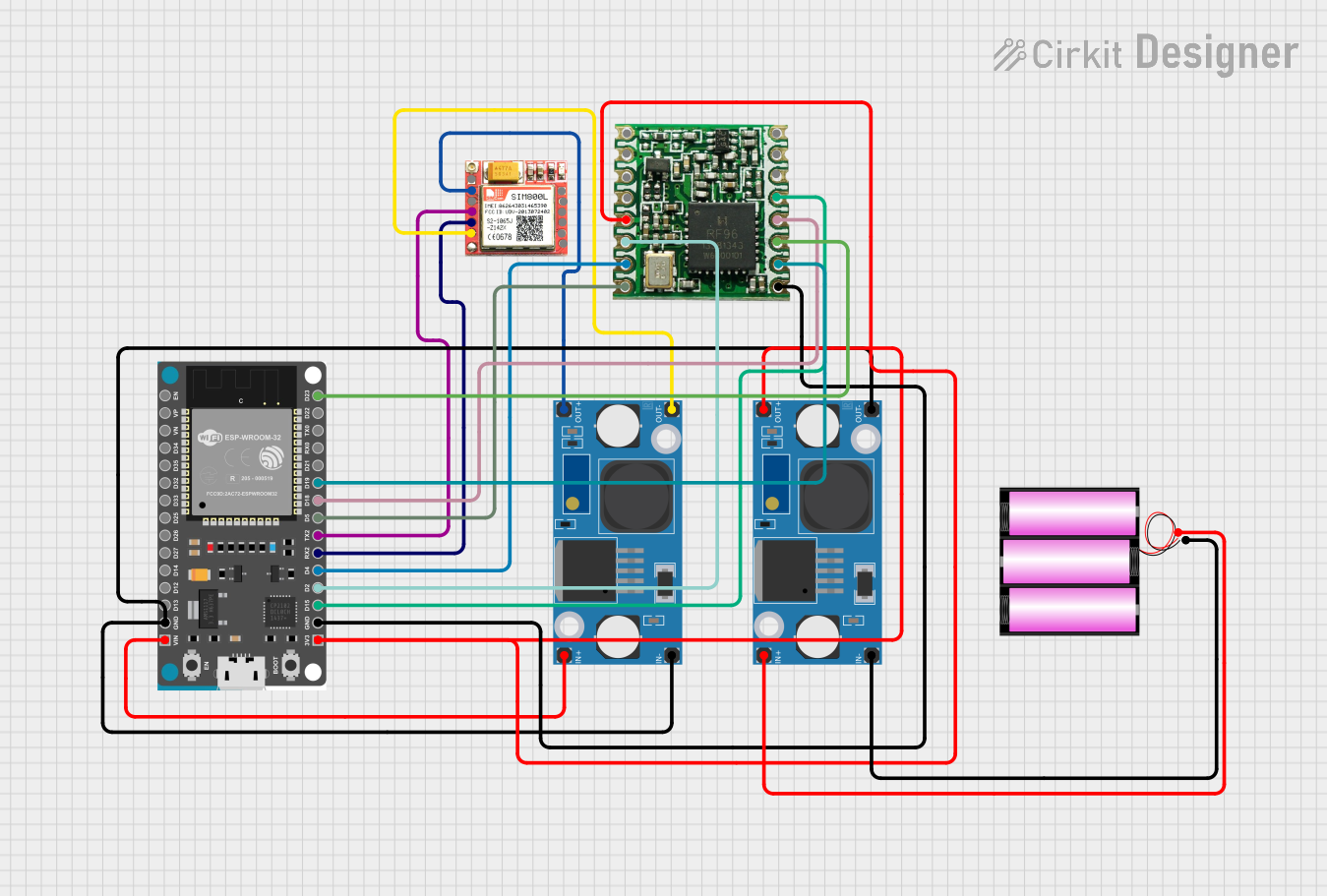
The circuit in question appears to be a communication system that integrates a microcontroller (ESP32 Devkit V1) with a GSM module (SIM800L) and a LoRa transceiver (RFM95). The system is powered by a 12V battery, which is stepped down to lower voltages using two LM2596 Step Down Modules to power the SIM800L and the ESP32/RFM95 respectively. The ESP32 is interfaced with the SIM800L for GSM communication and with the RFM95 for LoRa communication. The ESP32 facilitates data exchange between the GSM network and the LoRa network.
Component List
RFM95 LoRa Transceiver
- Description: A LoRa long-range wireless transceiver module.
- Pins: DIO2, DIO1, DIO0, 3.3V, DIO4, DIO3, GND, ANT, MISO, MOSI, SCK, NSS, RESET, DIO5
LM2596 Step Down Module
- Description: A voltage regulator module that steps down input voltage to a lower output voltage.
- Pins: OUT-, OUT+, IN-, IN+
SIM800L GSM Module
- Description: A GSM/GPRS module that allows cellular network communication.
- Pins: NFT, RING, VCC, DTR, RST, MIC +, RXD, MIC-, TXD, SPK+, GND, SPK-
ESP32 Devkit V1
- Description: A microcontroller with integrated Wi-Fi and Bluetooth, suitable for a variety of applications.
- Pins: 3V3, GND, D15, D2, D4, RX2, TX2, D5, D18, D19, D21, RX0, TX0, D22, D23, EN, VP, VN, D34, D35, D32, D33, D25, D26, D27, D14, D12, D13, VIN
Battery 12V
- Description: A 12V power source for the circuit.
- Pins: +, -
Wiring Details
RFM95 LoRa Transceiver
- 3.3V: Connected to 3.3V output from one of the LM2596 Step Down Modules.
- GND: Connected to the common ground.
- NSS: Connected to ESP32 pin D15.
- DIO0: Connected to ESP32 pin D2.
- DIO1: Connected to ESP32 pin D4.
- DIO2: Connected to ESP32 pin D5.
- SCK: Connected to ESP32 pin D18.
- MISO: Connected to ESP32 pin D19.
- MOSI: Connected to ESP32 pin D23.
LM2596 Step Down Modules
- OUT+: One module connected to SIM800L VCC, another to ESP32 3V3 and RFM95 3.3V.
- OUT-: Connected to the common ground.
- IN+: Connected to the positive terminal of the 12V battery.
- IN-: Connected to the negative terminal of the 12V battery and common ground.
SIM800L GSM Module
- VCC: Connected to the output of one of the LM2596 Step Down Modules.
- GND: Connected to the common ground.
- RXD: Connected to ESP32 pin TX2.
- TXD: Connected to ESP32 pin RX2.
ESP32 Devkit V1
- 3V3: Connected to the output of one of the LM2596 Step Down Modules.
- GND: Connected to the common ground.
- VIN: Connected to the output of one of the LM2596 Step Down Modules.
- TX2: Connected to SIM800L RXD.
- RX2: Connected to SIM800L TXD.
- D15, D2, D4, D5, D18, D19, D23: Connected to RFM95 as detailed above.
Battery 12V
- +: Connected to the input of both LM2596 Step Down Modules.
- -: Connected to the input of both LM2596 Step Down Modules and common ground.
Documented Code
There is no code provided for the microcontroller in this circuit. For a functional system, embedded code would be required to control the ESP32 Devkit V1, allowing it to communicate with the SIM800L GSM module and the RFM95 LoRa transceiver. The code would handle initialization of the modules, data exchange protocols, and power management, among other tasks. Since no code is available, this section cannot be completed.