
Wi-Fi Enabled Dual Load Cell Weight Measurement System with ESP32 and HX711
View and Edit Project In Cirkit Designer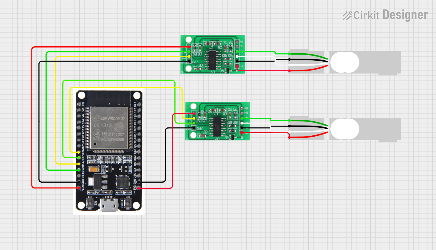
Circuit Documentation
Summary
This circuit involves the use of load cells, HX711 bridge sensor interfaces, and an ESP32 microcontroller. The load cells are used to measure weight, and the HX711 interfaces are used to amplify and convert the load cell signals to digital data. The ESP32 microcontroller processes this data and can be used for further applications such as wireless communication or data logging.
Component List
Load Cell - Red/white/black/green
- Description: A load cell used to measure weight.
- Pins: E+, A-, E-, A+
- Purpose in Circuit: Measures weight and provides analog signals.
HX711 - Bridge Sensor Interface
- Description: An interface for bridge sensors like load cells, providing amplification and analog-to-digital conversion.
- Pins: E+, E-, A-, A+, B-, B+, GND - GROUND, DATA (OUT), SCK - CLOCK (IN), 3.3/3.5V Supply
- Purpose in Circuit: Amplifies and converts the analog signals from the load cells to digital data.
ESP32
- Description: A microcontroller with built-in Wi-Fi and Bluetooth capabilities.
- Pins: EN, VP, VN, D34, D35, D32, D33, D25, D26, D27, D14, D12, D13, GND, VIN, 3V3, D15, D2, D4, RX2, TX2, D5, D18, D19, D21, RX0, TX0, D22, D23, BOOT
- Purpose in Circuit: Processes the digital data from the HX711 interfaces and can be used for further applications such as wireless communication or data logging.
Wiring Details
Load Cell - Red/white/black/green (1)
- E+ connected to E+ of HX711 - Bridge Sensor Interface (1)
- A- connected to A- of HX711 - Bridge Sensor Interface (1)
- E- connected to E- of HX711 - Bridge Sensor Interface (1)
- A+ connected to A+ of HX711 - Bridge Sensor Interface (1)
HX711 - Bridge Sensor Interface (1)
- E+ connected to E+ of Load Cell - Red/white/black/green (1)
- A- connected to A- of Load Cell - Red/white/black/green (1)
- E- connected to E- of Load Cell - Red/white/black/green (1)
- A+ connected to A+ of Load Cell - Red/white/black/green (1)
- GND - GROUND connected to GND of ESP32
- DATA (OUT) connected to D14 of ESP32
- SCK - CLOCK (IN) connected to D12 of ESP32
- 3.3/3.5V Supply connected to VIN of ESP32
ESP32
- GND connected to GND - GROUND of HX711 - Bridge Sensor Interface (1)
- D14 connected to DATA (OUT) of HX711 - Bridge Sensor Interface (1)
- D12 connected to SCK - CLOCK (IN) of HX711 - Bridge Sensor Interface (1)
- VIN connected to 3.3/3.5V Supply of HX711 - Bridge Sensor Interface (1)
- D26 connected to SCK - CLOCK (IN) of HX711 - Bridge Sensor Interface (2)
- D27 connected to DATA (OUT) of HX711 - Bridge Sensor Interface (2)
- 3V3 connected to 3.3/3.5V Supply of HX711 - Bridge Sensor Interface (2)
- GND connected to GND - GROUND of HX711 - Bridge Sensor Interface (2)
HX711 - Bridge Sensor Interface (2)
- E+ connected to E+ of Load Cell - Red/white/black/green (2)
- E- connected to E- of Load Cell - Red/white/black/green (2)
- A- connected to A- of Load Cell - Red/white/black/green (2)
- A+ connected to A+ of Load Cell - Red/white/black/green (2)
- SCK - CLOCK (IN) connected to D26 of ESP32
- DATA (OUT) connected to D27 of ESP32
- 3.3/3.5V Supply connected to 3V3 of ESP32
- GND - GROUND connected to GND of ESP32
Load Cell - Red/white/black/green (2)
- E+ connected to E+ of HX711 - Bridge Sensor Interface (2)
- E- connected to E- of HX711 - Bridge Sensor Interface (2)
- A- connected to A- of HX711 - Bridge Sensor Interface (2)
- A+ connected to A+ of HX711 - Bridge Sensor Interface (2)
Code
No code is provided for this circuit.