Raspberry Pi 5-Based Multi-Channel Audio System
Circuit Documentation
Summary
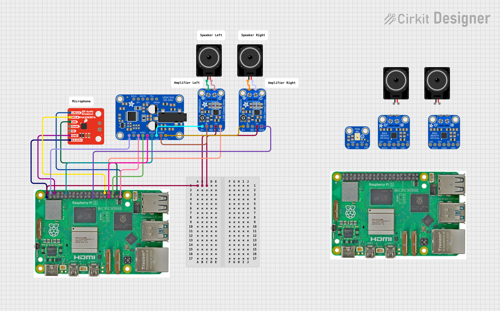
This circuit is designed to interface a Raspberry Pi 5 with various audio components to create an audio processing and output system. It includes digital-to-analog converters (DACs), amplifiers, and loudspeakers to output audio. The Raspberry Pi 5 serves as the central processing unit, controlling the flow of digital audio data through I2S communication to the DACs, which then convert the digital signals into analog signals. These analog signals are amplified by the PAM8302 amplifiers and output through the loudspeakers.
Component List
Raspberry Pi 5
- A microcomputer with multiple GPIO pins and dedicated power and ground pins. It serves as the central controller for the circuit.
SparkFun I2S Audio Breakout
- An I2S audio breakout board that allows for high-quality audio playback via the I2S protocol.
Adafruit PAM8302
- A mono audio amplifier designed for driving a single loudspeaker with high-quality sound.
Loudspeaker
- An electroacoustic transducer that converts an electrical audio signal into a corresponding sound.
Adafruit UDA1334 I2S DAC
- A high-quality I2S digital-to-analog converter that provides audio output from digital I2S signals.
Adafruit MAX98357A
- A Class D amplifier with an integrated DAC, designed for use with I2S digital audio signals.
Adafruit PDM Mic
- A digital microphone that captures audio and outputs a digital signal.
Wiring Details
Raspberry Pi 5
- 5V connected to VCC of both Adafruit PAM8302 amplifiers and VIN of Adafruit UDA1334 I2S DAC.
- 3.3V connected to VDD of SparkFun I2S Audio Breakout.
- GND connected to GND of SparkFun I2S Audio Breakout, Adafruit UDA1334 I2S DAC, and both Adafruit PAM8302 amplifiers.
- GPIO 18 connected to BITCLK_IN of Adafruit UDA1334 I2S DAC.
- GPIO 12 connected to BCLK of SparkFun I2S Audio Breakout.
- GPIO 20 connected to DIN of SparkFun I2S Audio Breakout.
- GPIO 21 connected to LRCLK of SparkFun I2S Audio Breakout.
- GPIO 13 connected to DATA_IN of Adafruit UDA1334 I2S DAC.
- GPIO 19 connected to WORDSEL_IN of Adafruit UDA1334 I2S DAC.
SparkFun I2S Audio Breakout
- GND connected to GND of Raspberry Pi 5.
- VDD connected to 3.3V of Raspberry Pi 5.
- BCLK connected to GPIO 12 of Raspberry Pi 5.
- DIN connected to GPIO 20 of Raspberry Pi 5.
- LRCLK connected to GPIO 21 of Raspberry Pi 5.
Adafruit PAM8302 (Instance 1)
- VCC connected to 5V of Raspberry Pi 5.
- GND connected to GND of Raspberry Pi 5.
- AIN+ connected to OUTL of Adafruit UDA1334 I2S DAC.
- VO+ and VO- connected to pin1 and pin2 of Loudspeaker (Instance 1), respectively.
Adafruit PAM8302 (Instance 2)
- VCC connected to 5V of Raspberry Pi 5.
- GND connected to GND of Raspberry Pi 5.
- AIN+ connected to OUTR of Adafruit UDA1334 I2S DAC.
- VO+ and VO- connected to pin1 and pin2 of Loudspeaker (Instance 2), respectively.
Loudspeaker (Instance 1)
- pin1 connected to VO+ of Adafruit PAM8302 (Instance 1).
- pin2 connected to VO- of Adafruit PAM8302 (Instance 1).
Loudspeaker (Instance 2)
- pin1 connected to VO+ of Adafruit PAM8302 (Instance 2).
- pin2 connected to VO- of Adafruit PAM8302 (Instance 2).
Adafruit UDA1334 I2S DAC
- VIN connected to 5V of Raspberry Pi 5.
- GND connected to GND of Raspberry Pi 5.
- BITCLK_IN connected to GPIO 18 of Raspberry Pi 5.
- DATA_IN connected to GPIO 13 of Raspberry Pi 5.
- WORDSEL_IN connected to GPIO 19 of Raspberry Pi 5.
- OUTL connected to AIN+ of Adafruit PAM8302 (Instance 1).
- OUTR connected to AIN+ of Adafruit PAM8302 (Instance 2).
Documented Code
Raspberry Pi 5 (Primary Microcontroller)
void setup() {
  // put your setup code here, to run once:

}

void loop() {
  // put your main code here, to run repeatedly:

}
Note: The actual implementation code for the Raspberry Pi 5 will depend on the specific audio processing and output requirements. The provided code is a template and will need to be filled in with the logic for initializing and controlling the I2S interface, as well as handling audio data.
Additional Microcontrollers
Note: The provided code snippets for additional microcontrollers are placeholders. Each microcontroller in the circuit will require specific code based on its role and functionality. The actual code will need to be developed according to the requirements of the circuit.
(Repeat the above note for each additional microcontroller instance provided in the input code list.)