Arduino-Controlled Interactive Buttons with MiniPC and Projector Display
Circuit Documentation
Summary of the Circuit
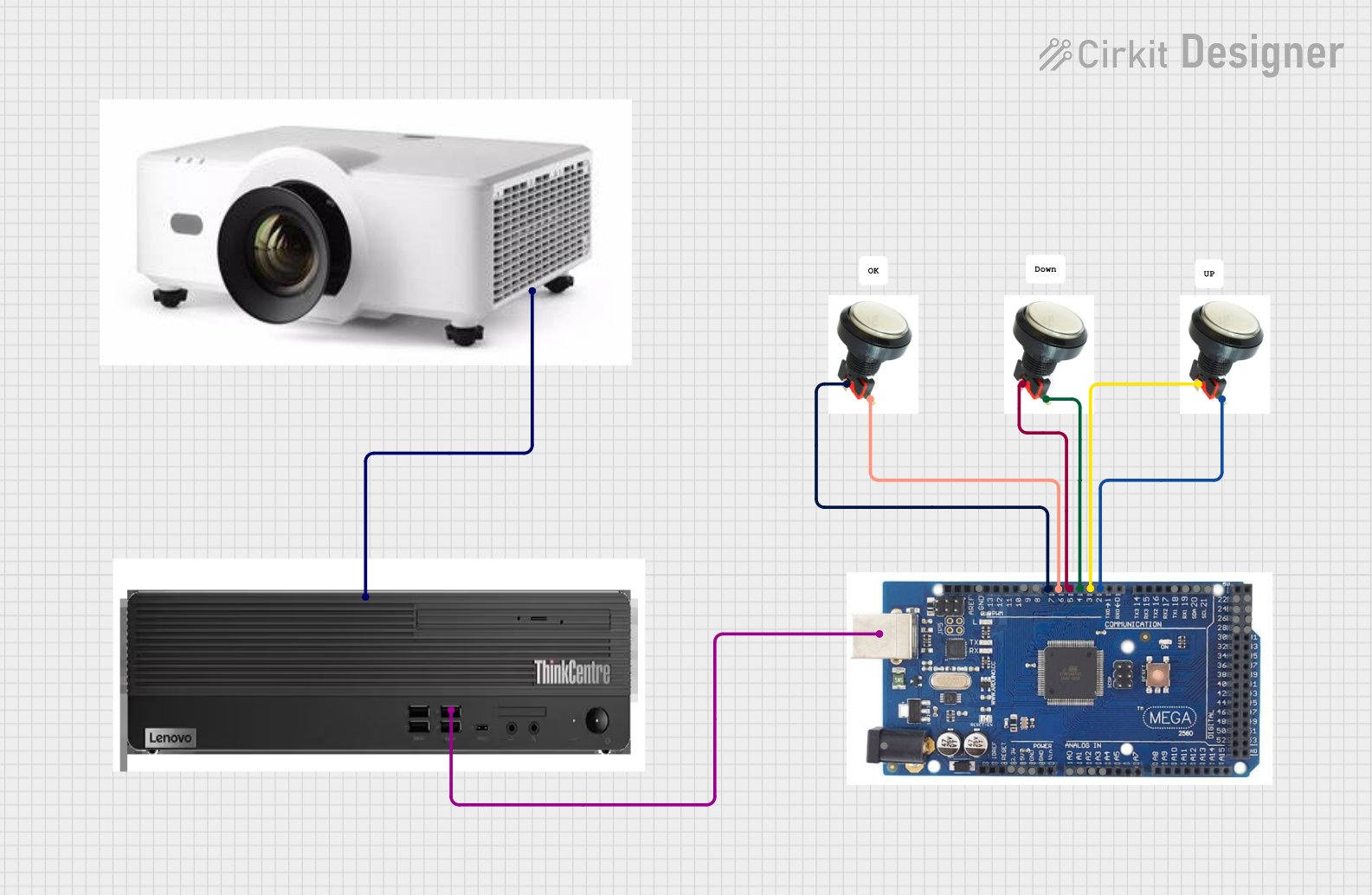
The circuit described by the provided inputs consists of an Arduino microcontroller interfaced with multiple buttons, a MiniPC, and a projector. The buttons are connected to specific digital input pins on the Arduino, which can be programmed to respond to button presses. The Arduino also has a USB connection to the MiniPC, allowing for serial communication or programming. Additionally, the MiniPC is connected to a projector via an HDMI connection, suggesting that the MiniPC may be used to send visual data to the projector.
Component List
Button
- Description: A standard push-button switch.
- Pins:
- Button: The pin connected to one terminal of the button.
- LED: The pin connected to an LED or an LED indicator circuit.
Arduino
- Description: A microcontroller board based on the ATmega328P (or similar, depending on the model).
- Pins:
- Digital I/O Pins: Pin2, Pin3, Pin4, Pin5, Pin6, Pin7, Pin8, Pin9
- Analog Input Pins: A0, A1, A2, A3
- Power Pins: GND, 5V, 3.3V, 12V
- Communication Pins: USB, SCL, SDA, RX, TX
- Additional Digital I/O Pins: Pin22, Pin23, Pin24, Pin25, Pin26, Pin27, Pin28, Pin29
MiniPC
- Description: A compact personal computer with USB and HDMI interfaces.
- Pins:
- USB: Universal Serial Bus interface for communication and power.
- HDMI: High-Definition Multimedia Interface for video and audio output.
Projector
- Description: A device that projects visual media from an input source.
- Pins:
- HDMI: High-Definition Multimedia Interface for receiving video and audio input.
Wiring Details
Button Wiring
- Button to Arduino: The button terminal is connected to a digital input pin on the Arduino.
- LED to Arduino: The LED terminal (or associated circuitry) is connected to another digital input pin on the Arduino.
Arduino Wiring
- USB to MiniPC: The USB pin on the Arduino is connected to the USB interface on the MiniPC, allowing for communication between the two devices.
MiniPC Wiring
- HDMI to Projector: The HDMI output from the MiniPC is connected to the HDMI input on the projector, enabling the projection of visual content from the MiniPC.
Documented Code
No code has been provided for the microcontrollers in the circuit. To fully utilize the hardware, embedded code for the Arduino should be written to handle button presses and communicate with the MiniPC. Additionally, software on the MiniPC would be required to process the Arduino's signals and output content to the projector.
Please note that the actual functionality of the circuit will depend on the specific code written for the Arduino and the software running on the MiniPC. The documentation above is based on the provided hardware connections and does not include any specific logic or behavior that would be implemented in the code.