Arduino-Controlled Robotics Platform with GPS, LIDAR, and ESP Communication Modules
Circuit Documentation
Summary
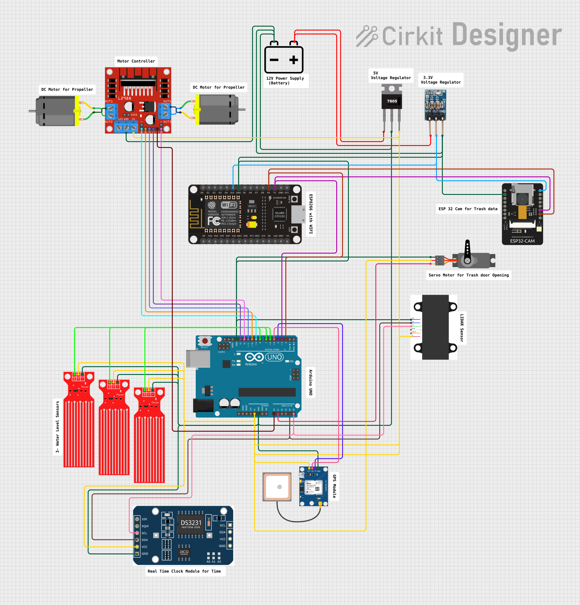
This circuit is composed of various sensors, actuators, power management components, and microcontrollers. It is designed to interface with motors, sensors, and communication modules to perform a range of functions, likely related to sensing, data acquisition, and control. The main controller appears to be an Arduino UNO, which is interfaced with a GPS module, a LIDAR sensor, a motor driver, a servo, an ESP32-CAM, voltage regulators, and multiple water level sensors. The circuit is powered by a 12V battery, with voltage regulation provided for components requiring 5V and 3.3V inputs.
Component List
Power Supply
- 12v Battery: Provides the main power source for the circuit.
- 7805 Voltage Regulator: Regulates voltage to 5V for components requiring this voltage level.
- 3.3V Regulator: Provides a 3.3V supply for components that operate at this voltage level.
Controllers
- Arduino UNO: Acts as the main microcontroller for managing inputs and outputs to various sensors and actuators.
- ESP-8266 Controller: A Wi-Fi capable microcontroller for wireless communication.
- ESP32 - CAM: A camera module with Wi-Fi capabilities, likely used for image capture and processing.
Sensors
- SparkFun Accessories LIDAR-Lite v3: A compact, high-performance optical distance measurement sensor.
- GPS NEO 6M: A GPS module for location tracking.
- Water Level Sensor: Used to detect the level of water in a container or environment. Three instances of this sensor are used in the circuit.
- rtc MODULE: A real-time clock module for timekeeping.
Actuators
- L298N DC Motor Driver: An H-bridge motor driver for controlling the direction and speed of DC motors.
- Servo: A small rotary actuator controlled by PWM signals.
- DC Motor: Two instances of DC motors controlled by the motor driver.
Miscellaneous
- Comments: Several comment components are included, which are placeholders for additional notes or instructions.
Wiring Details
Power Distribution
12v Battery:
+to 7805Vinand 3.3V RegulatorVin-to GND of all components requiring ground connection.
7805 Voltage Regulator:
Vinfrom 12v Battery+Gndto common groundVoutto 5V inputs of Arduino UNO and other 5V components.
3.3V Regulator:
Vinfrom 12v Battery+GNDto common groundOUTto 3.3V inputs of ESP-8266 Controller and ESP32 - CAM.
Controllers
- Arduino UNO:
GNDto common ground5Vto 5V componentsA0to L298NIN4A1to ServoPWMA4to LIDARSDA (blue)and rtc MODULESDAA5to LIDARSCL (green)and rtc MODULESCLD2toRXof ESP-8266 andVOTof ESP32 - CAMD3toTXof ESP-8266 andVORof ESP32 - CAMD4toTXof GPS NEO 6MD5toRXof GPS NEO 6MD6to Water Level Sensor SIGD7to Water Level Sensor SIGD8to Water Level Sensor SIGD9to L298NENAD10to L298NIN1D11to L298NIN2D12to L298NENBD13to L298NIN3
Sensors and Actuators
L298N DC Motor Driver:
GNDto common ground5Vfrom Arduino UNO5V12Vfrom 12v Battery+IN1,IN2,IN3,IN4,ENA,ENBcontrolled by Arduino UNOOUT1,OUT2to DC MotorOUT3,OUT4to DC Motor
Servo:
GNDto common groundVCCfrom Arduino UNO5VPWMcontrolled by Arduino UNOA1
Water Level Sensors:
GNDto common groundVCCfrom Arduino UNO5VSIGto Arduino UNOD6,D7,D8
GPS NEO 6M:
GNDto common groundVCCfrom Arduino UNO5VRXto Arduino UNOD5TXto Arduino UNOD4
SparkFun Accessories LIDAR-Lite v3:
GNDto common ground5V (red)from Arduino UNO5VSDA (blue)to Arduino UNOA4SCL (green)to Arduino UNOA5
rtc MODULE:
GNDto common groundVCCfrom Arduino UNO5VSDAto Arduino UNOA4SCLto Arduino UNOA5
DC Motors:
pin 1andpin 2connected to L298NOUT1,OUT2,OUT3,OUT4
Communication Modules
ESP-8266 Controller:
GNDto common ground3V3from 3.3V RegulatorOUTRXto Arduino UNOD2TXto Arduino UNOD3
ESP32 - CAM:
GNDto common ground3V3from 3.3V RegulatorOUTVOTto Arduino UNOD2VORto Arduino UNOD3
Documented Code
Arduino UNO Code (sketch.ino)
void setup() {
  // put your setup code here, to run once:

}

void loop() {
  // put your main code here, to run repeatedly:

}
Note: The provided code for the Arduino UNO is a template with empty setup and loop functions. The actual functionality needs to be implemented based on the specific requirements of the circuit.