
Arduino UNO Rain Detection System with LED Indicator and Buzzer Alert
View and Edit Project In Cirkit Designer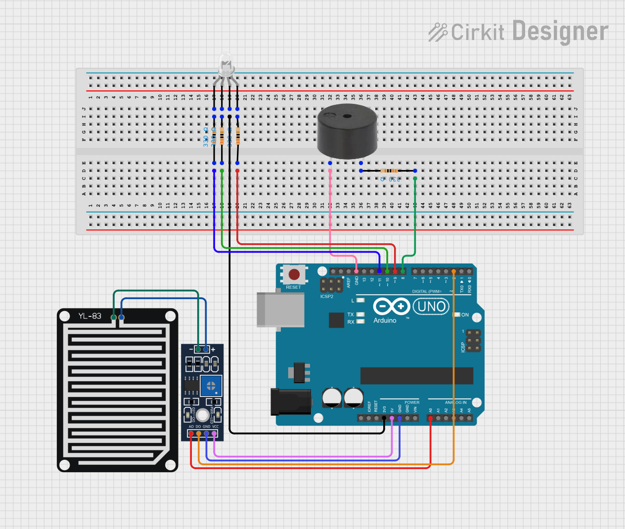
Circuit Documentation
Summary
This circuit is designed to interface an Arduino UNO with a YL-83 Rain Sensor, an LED, and a buzzer. The Arduino reads analog and digital signals from the rain sensor and controls the LED and buzzer based on the sensor readings. The circuit includes resistors to limit current to the LED and buzzer.
Component List
Arduino UNO
- Description: A microcontroller board based on the ATmega328P.
- Pins: UNUSED, IOREF, Reset, 3.3V, 5V, GND, Vin, A0, A1, A2, A3, A4, A5, SCL, SDA, AREF, D13, D12, D11, D10, D9, D8, D7, D6, D5, D4, D3, D2, D1, D0
YL-83 Rain Sensor - Detection Board
- Description: A sensor board that detects rain.
- Pins: POS, NEG
YL-83 Rain Sensor - Control Board
- Description: A control board for the YL-83 Rain Sensor.
- Pins: VCC, GND, DO, AO, POS, NEG
Resistor (330 Ohms)
- Description: A resistor with a resistance of 330 Ohms.
- Pins: pin1, pin2
LED: Four Pin
- Description: A four-pin LED with red, green, and blue cathodes and a common anode.
- Pins: red cathode, common anode, green cathode, blue cathode
Buzzer
- Description: A simple buzzer.
- Pins: PIN, GND
Wiring Details
Arduino UNO
- D11 connected to pin1 of a 330 Ohm resistor.
- D10 connected to pin1 of a 330 Ohm resistor.
- 3.3V connected to green cathode of the LED.
- D9 connected to pin1 of a 330 Ohm resistor.
- GND connected to PIN of the buzzer.
- D8 connected to pin1 of a 330 Ohm resistor.
- 5V connected to VCC of the YL-83 Rain Sensor - Control Board.
- GND connected to GND of the YL-83 Rain Sensor - Control Board.
- A0 connected to AO of the YL-83 Rain Sensor - Control Board.
- D2 connected to DO of the YL-83 Rain Sensor - Control Board.
YL-83 Rain Sensor - Detection Board
- NEG connected to POS of the YL-83 Rain Sensor - Control Board.
- POS connected to NEG of the YL-83 Rain Sensor - Control Board.
Resistor (330 Ohms)
- pin1 connected to D11 of the Arduino UNO.
- pin2 connected to red cathode of the LED.
LED: Four Pin
- red cathode connected to pin2 of a 330 Ohm resistor.
- common anode connected to pin2 of a 330 Ohm resistor.
- blue cathode connected to pin2 of a 330 Ohm resistor.
Buzzer
- PIN connected to GND of the Arduino UNO.
- GND connected to pin2 of a 330 Ohm resistor.
Documented Code
int sensor_A0 = A0; // conexión de A0 en el sensor a A0 en Arduino

int sensor_D0 = 2; // conexión de D0 en el sensor a la clavija 2 en Arduino

int valor_A0; // variable para el valor A0

int valor_D0; // variable para el valor A0

void setup() {
    Serial.begin(9600); // correr el monitor de serie
    pinMode(2, INPUT); // ajustando el pin 2 como entrada
}

void loop() {
    valor_A0 = analogRead(sensor_A0); // descargando valor desde A0
    valor_D0 = digitalRead(sensor_D0); // descargando valor de D0

    Serial.print("D0: "); // visualización en un monitor serial
    Serial.print(valor_D0);
    Serial.print(" -- A0: ");
    Serial.println(valor_A0);
    delay(200); // retraso entre lecturas consecutivas
}
This code initializes the Arduino to read analog and digital values from the YL-83 Rain Sensor and prints these values to the serial monitor. The setup function sets up the serial communication and configures the digital pin as an input. The loop function continuously reads the sensor values and prints them to the serial monitor with a delay of 200 milliseconds between readings.