
Arduino and XBEE Controlled Dual Motor System with Photoresistor and Pushbutton Inputs
View and Edit Project In Cirkit Designer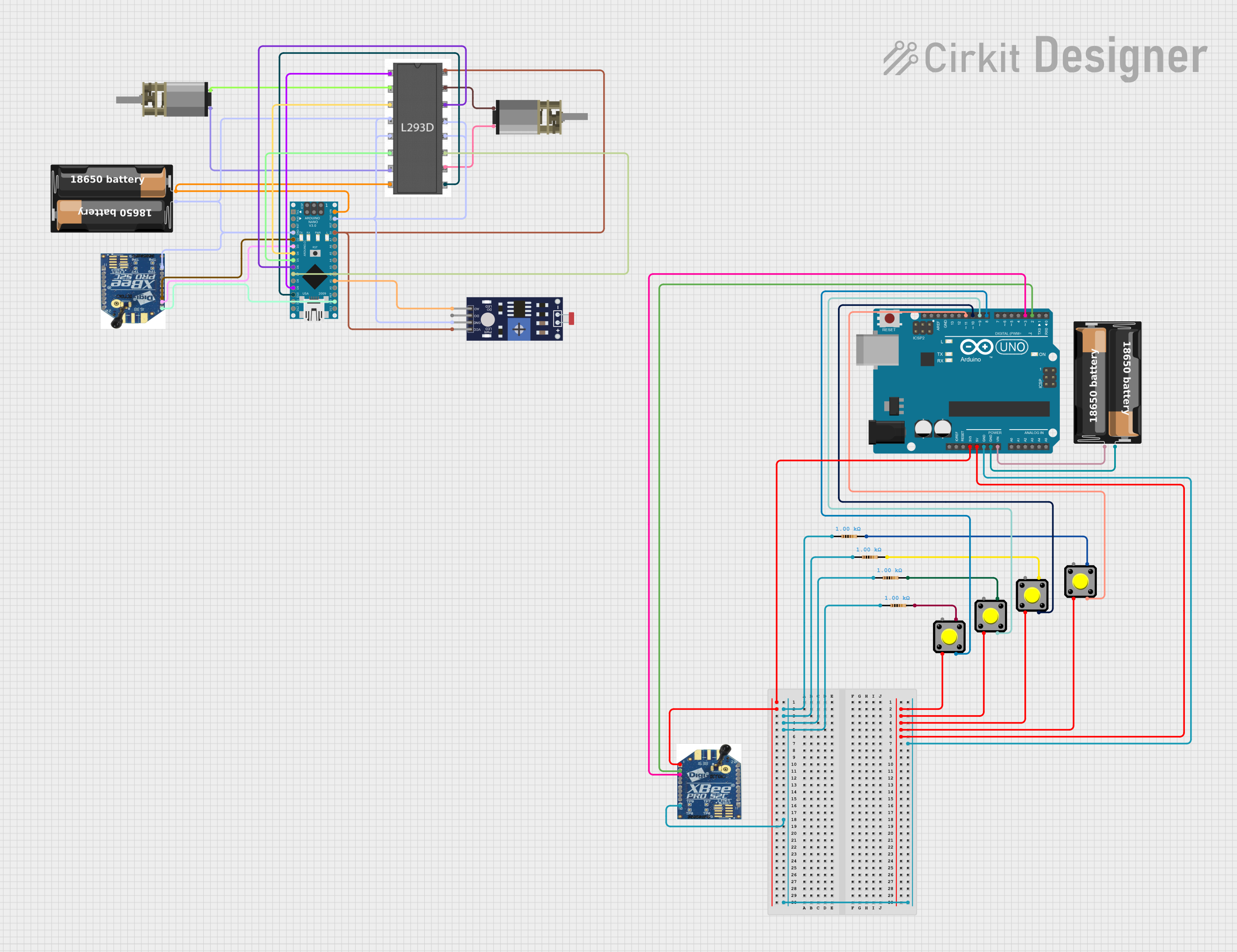
Circuit Documentation
Summary
This document provides a detailed overview of a circuit that includes various components such as an Arduino Nano, Arduino UNO, L293D motor driver, XBEE modules, DC motors, pushbuttons, resistors, a photoresistor sensor, and a battery case. The circuit is designed to control DC motors and communicate wirelessly using XBEE modules. The Arduino microcontrollers are programmed to manage the operations of the motors and sensors.
Component List
Arduino Nano
- Description: A small, complete, and breadboard-friendly board based on the ATmega328P.
- Pins: D1/TX, D0/RX, RESET, GND, D2, D3, D4, D5, D6, D7, D8, D9, D10, D11/MOSI, D12/MISO, VIN, 5V, A7, A6, A5, A4, A3, A2, A1, A0, AREF, 3V3, D13/SCK
Arduino UNO
- Description: A microcontroller board based on the ATmega328P.
- Pins: UNUSED, IOREF, Reset, 3.3V, 5V, GND, Vin, A0, A1, A2, A3, A4, A5, SCL, SDA, AREF, D13, D12, D11, D10, D9, D8, D7, D6, D5, D4, D3, D2, D1, D0
L293D Motor Driver
- Description: A quadruple high-current half-H driver designed to drive inductive loads such as relays, solenoids, DC and bipolar stepping motors.
- Pins: Enable 1,2, Input 1, Output 1, GND, Output 2, Input 2, Vcc2, Vcc1, Input 4, Output 4, Output 3, Input 3, Enable 3,4
XBEE S2C
- Description: A wireless communication module based on the Zigbee protocol.
- Pins: Vcc, DOUT, DIN/CONFIG, DIO12, RESET, PWM, DIO 11, RESERVED, DTR, GND, AD0, AD1, AD2, AD3, RTS, ASC, VREF, ON/SLEEP, CTS/DIO7, DIO4
DC Mini Metal Gear Motor
- Description: A small DC motor with metal gears for increased torque.
- Pins: IN1, IN2
Pushbutton
- Description: A simple pushbutton switch.
- Pins: Pin 2, Pin 1, Pin 3, Pin 4
Photoresistor (LDR) Sensor (Wokwi Compatible)
- Description: A light-dependent resistor sensor.
- Pins: VCC, GND, DO, AO
Resistor
- Description: A passive electrical component that implements electrical resistance.
- Pins: pin1, pin2
- Properties: Resistance: 1000 Ohms
My Battery Case
- Description: A battery holder for powering the circuit.
- Pins: +, -
Wiring Details
Arduino Nano
- D9 connected to Enable 1,2 of L293D
- D4 connected to Output 1 of L293D
- D5 connected to Output 2 of L293D
- D6 connected to Output 4 of L293D
- D7 connected to Output 3 of L293D
- D10 connected to Enable 3,4 of L293D
- D2 connected to DIN/CONFIG of XBEE S2C
- D3 connected to DOUT of XBEE S2C
- A1 connected to AO of Photoresistor (LDR) Sensor
- VIN connected to Vcc2 of L293D and + of My Battery Case
- 5V connected to VCC of Photoresistor (LDR) Sensor
- 3V3 connected to Vcc of XBEE S2C
- GND connected to GND of XBEE S2C, GND of Photoresistor (LDR) Sensor, GND of L293D, and - of My Battery Case
Arduino UNO
- 3.3V connected to Vcc of XBEE S2C
- D2 connected to DOUT of XBEE S2C
- D3 connected to DIN/CONFIG of XBEE S2C
- D11 connected to Pin 3 of Pushbutton
- D10 connected to Pin 3 of Pushbutton
- D9 connected to Pin 3 of Pushbutton
- D8 connected to Pin 3 of Pushbutton
- 5V connected to Pin 2 of Pushbutton
- GND connected to GND of XBEE S2C and + of My Battery Case
- Vin connected to - of My Battery Case
L293D Motor Driver
- Enable 1,2 connected to D9 of Arduino Nano
- Input 1 connected to IN2 of DC Mini Metal Gear Motor
- Output 1 connected to D4 of Arduino Nano
- Output 2 connected to D5 of Arduino Nano
- Input 2 connected to IN1 of DC Mini Metal Gear Motor
- Vcc2 connected to VIN of Arduino Nano and + of My Battery Case
- Vcc1 connected to 5V of Arduino Nano
- Input 4 connected to IN1 of DC Mini Metal Gear Motor
- Output 4 connected to D6 of Arduino Nano
- Output 3 connected to D7 of Arduino Nano
- Input 3 connected to IN2 of DC Mini Metal Gear Motor
- Enable 3,4 connected to D10 of Arduino Nano
- GND connected to GND of Arduino Nano, GND of My Battery Case
XBEE S2C
- Vcc connected to 3.3V of Arduino UNO
- GND connected to GND of Arduino UNO
- DIN/CONFIG connected to D3 of Arduino UNO
- DOUT connected to D2 of Arduino UNO
DC Mini Metal Gear Motor
- IN1 connected to Input 2 of L293D
- IN2 connected to Input 1 of L293D
Pushbutton
- Pin 2 connected to 5V of Arduino UNO
- Pin 3 connected to D11, D10, D9, D8 of Arduino UNO
- Pin 4 connected to pin2 of Resistor
Photoresistor (LDR) Sensor
- VCC connected to 5V of Arduino Nano
- GND connected to GND of Arduino Nano
- AO connected to A1 of Arduino Nano
Resistor
- pin1 connected to pin1 of other resistors and GND of XBEE S2C and Arduino UNO
- pin2 connected to Pin 4 of Pushbutton
My Battery Case
- + connected to VIN of Arduino Nano and Vcc2 of L293D
- - connected to GND of Arduino Nano and GND of L293D
Documented Code
Arduino Nano Code
void setup() {
  // put your setup code here, to run once:

}

void loop() {
  // put your main code here, to run repeatedly:

}
Arduino UNO Code
void setup() {
  // put your setup code here, to run once:

}

void loop() {
  // put your main code here, to run repeatedly:

}
This documentation provides a comprehensive overview of the circuit, including the components used, their wiring details, and the code for the microcontrollers.