
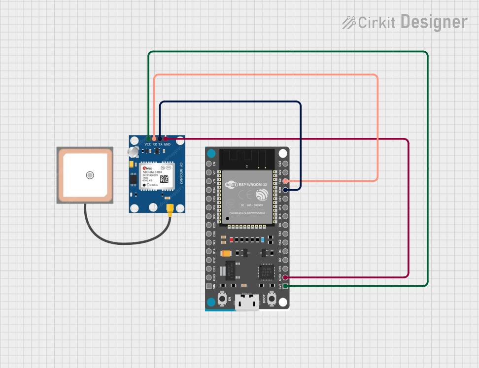
Circuit Documentation
Summary
This document provides a detailed overview of a circuit that integrates a GPS NEO 6M module with an ESP32 Devkit V1 microcontroller. The ESP32 Devkit V1 is responsible for processing the GPS data and communicating it via a serial interface. The GPS module receives satellite signals to determine the geographical location, which is then sent to the ESP32 for parsing and output.
Component List
GPS NEO 6M
- Description: A GPS module capable of providing geographical coordinates.
- Pins:
- VCC: Power supply input.
- RX: Serial data receive pin.
- TX: Serial data transmit pin.
- GND: Ground connection.
ESP32 Devkit V1
- Description: A microcontroller development board with WiFi and Bluetooth capabilities.
- Pins:
- 3V3: 3.3V power output.
- GND: Ground connection.
- D15, D2, D4, D5, D18, D19, D21, D22, D23, D25, D26, D27, D14, D12, D13: General purpose input/output pins.
- RX2, TX2: Serial communication pins (unused in this circuit).
- RX0, TX0: Serial communication pins used for GPS communication.
- EN: Chip enable pin.
- VP, VN: Sensor voltage pins (unused in this circuit).
- D34, D35, D32, D33: Input-only pins (unused in this circuit).
- VIN: Voltage input for the board.
Wiring Details
GPS NEO 6M
- VCC connected to ESP32 Devkit V1 3V3.
- RX connected to ESP32 Devkit V1 TX0.
- TX connected to ESP32 Devkit V1 RX0.
- GND connected to ESP32 Devkit V1 GND.
ESP32 Devkit V1
- 3V3 connected to GPS NEO 6M VCC.
- TX0 connected to GPS NEO 6M RX.
- RX0 connected to GPS NEO 6M TX.
- GND connected to GPS NEO 6M GND.
Documented Code
The following code is written for the ESP32 Devkit V1 microcontroller to interface with the GPS NEO 6M module. The code initializes the serial communication with the GPS module, reads the GPS data, and outputs the latitude, longitude, altitude, and number of satellites to the serial monitor.
#include <HardwareSerial.h>
#include <TinyGPS++.h>

// Create an instance of the GPS
TinyGPSPlus gps;

// Set up the serial port for GPS communication
HardwareSerial mySerial(1);

// Define the GPS serial baud rate
const long GPS_BAUD = 9600;

void setup() {
  // Start the Serial Monitor at 115200 baud rate
  Serial.begin(9600);

  // Start the hardware serial port 1 for GPS communication at 9600 baud rate
  mySerial.begin(GPS_BAUD, SERIAL_8N1, 3, 1);  // Using pins 16 for RX, 17 for TX

  Serial.println("GPS Module Test Started!");
}

void loop() {
  // Feed the GPS data to TinyGPS++ library
  while (mySerial.available() > 0) {
    gps.encode(mySerial.read());

    // If a new GPS fix is available
    if (gps.location.isUpdated()) {
      // Print the location information
      Serial.print("Latitude= ");
      Serial.print(gps.location.lat(), 6);
      Serial.print(" Longitude= ");
      Serial.println(gps.location.lng(), 6);

      // Print altitude and other GPS info
      Serial.print("Altitude= ");
      Serial.println(gps.altitude.meters());

      Serial.print("Satellites= ");
      Serial.println(gps.satellites.value());
    }
  }

  // Small delay to avoid overwhelming the serial monitor
  delay(100);
}
This code is saved in a file named sketch.ino and is intended to be uploaded to the ESP32 Devkit V1 microcontroller using the Arduino IDE or a similar development environment.