
Arduino Nano-Based IR-Controlled Stepper Motor System with Pushbutton Interface
View and Edit Project In Cirkit Designer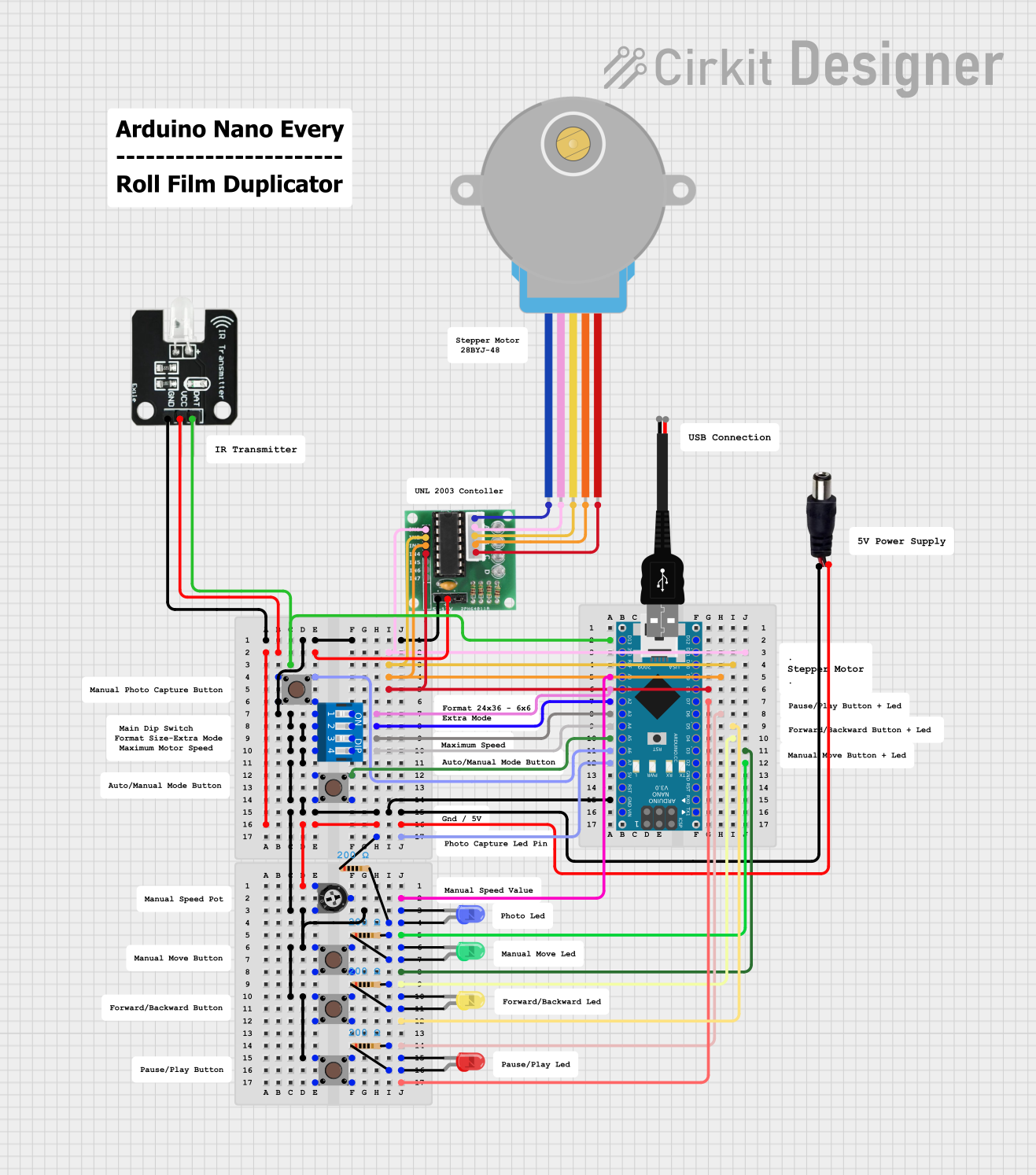
Circuit Documentation
Summary
This document provides a detailed overview of a circuit that includes various components such as an Arduino Nano, IR Transmitter, stepper motor, pushbuttons, LEDs, resistors, and more. The circuit is designed to interface these components to perform specific tasks, controlled by the Arduino Nano microcontroller.
Component List
Power Jack
- Pins: POSITIF, NEGATIF
- Description: Provides power to the circuit.
IR Transmitter
- Pins: DAT, VCC, GND
- Description: Transmits infrared signals.
28BYJ-48 Stepper Motor
- Pins: BLUE, PINK, YELLOW, ORANGE, RED
- Description: A stepper motor used for precise control of rotation.
ULN 2003
- Pins: IN1, IN2, IN3, IN4, IN5, IN6, IN7, GND, +, COIL1, COIL2, COIL3, COIL4, COIL5
- Description: A Darlington transistor array used to drive the stepper motor.
Arduino Nano
- Pins: D1/TX, D0/RX, RESET, GND, D2, D3, D4, D5, D6, D7, D8, D9, D10, D11/MOSI, D12/MISO, VIN, 5V, A7, A6, A5, A4, A3, A2, A1, A0, AREF, 3V3, D13/SCK
- Description: A microcontroller used to control the circuit.
Pushbutton
- Pins: Pin 3 (out), Pin 4 (out), Pin 1 (in), Pin 2 (in)
- Description: A simple pushbutton switch.
DIP Switch 4 Position
- Pins: 1, 2, 3, 4, 5, 6, 7, 8
- Description: A 4-position DIP switch.
Trimmer Potentiometer
- Pins: leg1, wiper, leg2
- Description: A variable resistor used to adjust resistance.
- Properties: Resistance: 10000 Ohms
LED: Two Pin (green)
- Pins: cathode, anode
- Description: A green LED.
LED: Two Pin (yellow)
- Pins: cathode, anode
- Description: A yellow LED.
LED: Two Pin (blue)
- Pins: cathode, anode
- Description: A blue LED.
LED: Two Pin (red)
- Pins: cathode, anode
- Description: A red LED.
Resistor
- Pins: pin1, pin2
- Description: A resistor.
- Properties: Resistance: 200 Ohms
USB male 2 pin connection
- Pins: Negative -, Positive +
- Description: A USB male connector.
Wiring Details
Power Jack
NEGATIF is connected to:
- Trimmer Potentiometer (leg1)
- IR Transmitter (VCC)
- ULN 2003 (+)
POSITIF is connected to:
- Arduino Nano (GND)
- Pushbutton (Pin 2 (in))
- Trimmer Potentiometer (leg2)
- Pushbutton (Pin 2 (in))
- Pushbutton (Pin 2 (in))
- LED: Two Pin (blue) (cathode)
- Pushbutton (Pin 4 (out))
- Pushbutton (Pin 3 (out))
- Pushbutton (Pin 4 (out))
- DIP Switch 4 Position (1)
- DIP Switch 4 Position (2)
- DIP Switch 4 Position (3)
- DIP Switch 4 Position (4)
- IR Transmitter (GND)
- ULN 2003 (GND)
IR Transmitter
DAT is connected to:
- Arduino Nano (D13/SCK)
VCC is connected to:
- Power Jack (NEGATIF)
GND is connected to:
- Power Jack (POSITIF)
28BYJ-48 Stepper Motor
BLUE is connected to:
- ULN 2003 (COIL1)
PINK is connected to:
- ULN 2003 (COIL2)
YELLOW is connected to:
- ULN 2003 (COIL3)
ORANGE is connected to:
- ULN 2003 (COIL4)
RED is connected to:
- ULN 2003 (COIL5)
ULN 2003
IN1 is connected to:
- Arduino Nano (D11/MOSI)
IN2 is connected to:
- Arduino Nano (D10)
IN3 is connected to:
- Arduino Nano (D9)
IN4 is connected to:
- Arduino Nano (D8)
COIL1 is connected to:
- 28BYJ-48 Stepper Motor (BLUE)
COIL2 is connected to:
- 28BYJ-48 Stepper Motor (PINK)
COIL3 is connected to:
- 28BYJ-48 Stepper Motor (YELLOW)
COIL4 is connected to:
- 28BYJ-48 Stepper Motor (ORANGE)
COIL5 is connected to:
- 28BYJ-48 Stepper Motor (RED)
GND is connected to:
- Power Jack (POSITIF)
+ is connected to:
- Power Jack (NEGATIF)
Arduino Nano
A0 is connected to:
- Trimmer Potentiometer (wiper)
GND is connected to:
- Power Jack (POSITIF)
D2 is connected to:
- Resistor (pin2)
D3 is connected to:
- Pushbutton (Pin 3 (out))
D4 is connected to:
- Resistor (pin2)
D5 is connected to:
- Pushbutton (Pin 3 (out))
D6 is connected to:
- Resistor (pin2)
D7 is connected to:
- Pushbutton (Pin 3 (out))
D13/SCK is connected to:
- IR Transmitter (DAT)
D11/MOSI is connected to:
- ULN 2003 (IN1)
D10 is connected to:
- ULN 2003 (IN2)
D9 is connected to:
- ULN 2003 (IN3)
D8 is connected to:
- ULN 2003 (IN4)
A1 is connected to:
- DIP Switch 4 Position (8)
A2 is connected to:
- DIP Switch 4 Position (7)
A3 is connected to:
- DIP Switch 4 Position (6)
A4 is connected to:
- DIP Switch 4 Position (5)
A5 is connected to:
- Pushbutton (Pin 1 (in))
A6 is connected to:
- Pushbutton (Pin 1 (in))
- Pushbutton (Pin 2 (in))
A7 is connected to:
- Resistor (pin1)
Pushbutton
Pin 3 (out) is connected to:
- Arduino Nano (D3)
- Arduino Nano (D5)
- Arduino Nano (D7)
Pin 4 (out) is connected to:
- Power Jack (POSITIF)
Pin 1 (in) is connected to:
- LED: Two Pin (green) (cathode)
- LED: Two Pin (yellow) (cathode)
- LED: Two Pin (red) (cathode)
- Arduino Nano (A5)
- Arduino Nano (A6)
Pin 2 (in) is connected to:
- Arduino Nano (GND)
- Power Jack (POSITIF)
DIP Switch 4 Position
1 is connected to:
- Power Jack (POSITIF)
2 is connected to:
- Power Jack (POSITIF)
3 is connected to:
- Power Jack (POSITIF)
4 is connected to:
- Power Jack (POSITIF)
5 is connected to:
- Arduino Nano (A4)
6 is connected to:
- Arduino Nano (A3)
7 is connected to:
- Arduino