
Arduino-Based RF-Controlled MOSFET Switch with Battery Power
View and Edit Project In Cirkit Designer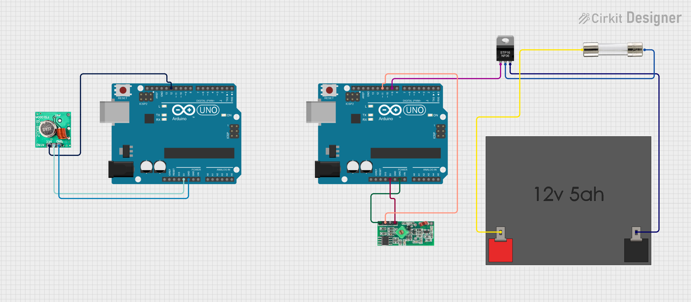
Circuit Documentation
Summary
This circuit consists of two Arduino UNO microcontrollers, an FS1000A 433MHz RF Transmitter, a 433 MHz RF Receiver Module, an STP16NF06 N-Channel Power MOSFET, a 12V 5Ah Battery, and a Fuse. The circuit is designed to send and receive RF signals to control a MOSFET, which in turn controls the power to a transmitter.
Component List
Arduino UNO
- Description: A microcontroller board based on the ATmega328P.
- Pins: UNUSED, IOREF, Reset, 3.3V, 5V, GND, Vin, A0, A1, A2, A3, A4, A5, SCL, SDA, AREF, D13, D12, D11, D10, D9, D8, D7, D6, D5, D4, D3, D2, D1, D0
FS1000A 433MHz RF Transmitter
- Description: A 433MHz RF transmitter module.
- Pins: DATA, VCC, GND, ANT
433 MHz RF Receiver Module
- Description: A 433MHz RF receiver module.
- Pins: VCC, DATA, GND
STP16NF06 N-Channel Power MOSFET
- Description: An N-channel power MOSFET.
- Pins: gate, drain, source
12V 5Ah Battery
- Description: A 12V 5Ah rechargeable battery.
- Pins: 12v +, 12v -
Fuse
- Description: A fuse for overcurrent protection.
- Pins: Terminal 1, Terminal 2
Wiring Details
Arduino UNO (Transmitter)
- 5V connected to VCC of FS1000A 433MHz RF Transmitter
- GND connected to GND of FS1000A 433MHz RF Transmitter
- D12 connected to DATA of FS1000A 433MHz RF Transmitter
Arduino UNO (Receiver)
- 5V connected to VCC of 433 MHz RF Receiver Module
- GND connected to GND of 433 MHz RF Receiver Module
- D11 connected to DATA of 433 MHz RF Receiver Module
- D9 connected to gate of STP16NF06 N-Channel Power MOSFET
FS1000A 433MHz RF Transmitter
- VCC connected to 5V of Arduino UNO (Transmitter)
- GND connected to GND of Arduino UNO (Transmitter)
- DATA connected to D12 of Arduino UNO (Transmitter)
433 MHz RF Receiver Module
- VCC connected to 5V of Arduino UNO (Receiver)
- GND connected to GND of Arduino UNO (Receiver)
- DATA connected to D11 of Arduino UNO (Receiver)
STP16NF06 N-Channel Power MOSFET
- gate connected to D9 of Arduino UNO (Receiver)
- drain connected to Terminal 2 of Fuse
- source connected to 12v - of 12V 5Ah Battery
12V 5Ah Battery
- 12v + connected to Terminal 1 of Fuse
- 12v - connected to source of STP16NF06 N-Channel Power MOSFET
Fuse
- Terminal 1 connected to 12v + of 12V 5Ah Battery
- Terminal 2 connected to drain of STP16NF06 N-Channel Power MOSFET
Code Documentation
Arduino UNO (Transmitter)
/*
 * This Arduino sketch sends a 'yes' or 'no' signal using the RF transmitter.
 * '0' represents 'no' and '1' represents 'yes'.
 */

#include <VirtualWire.h>

const int transmitPin = 12; // Pin connected to DATA pin of RF transmitter

void setup() {
  vw_set_tx_pin(transmitPin); // Set the transmit pin
  vw_setup(2000); // Bits per second
}

void loop() {
  sendSignal(1); // Send 'yes' signal
  delay(1000); // Wait for 1 second
  sendSignal(0); // Send 'no' signal
  delay(1000); // Wait for 1 second
}

void sendSignal(uint8_t signal) {
  vw_send(&signal, 1); // Send the signal
  vw_wait_tx(); // Wait until the message is sent
}
Arduino UNO (Receiver)
/*
 * This Arduino sketch controls a MOSFET based on RF receiver input.
 * When a 'yes' signal (1) is received, it sends voltage to the transmitter
 * connected to pin D9. When a 'no' signal (0) is received, it turns off the
 * voltage to the transmitter.
 */

#include <VirtualWire.h>

const int receiverPin = 11; // Pin connected to DATA pin of RF receiver
const int mosfetPin = 9; // Pin connected to gate of MOSFET

void setup() {
  pinMode(mosfetPin, OUTPUT); // Set MOSFET pin as output
  vw_set_rx_pin(receiverPin); // Set the receive pin
  vw_setup(2000); // Bits per second
  vw_rx_start(); // Start the receiver
}

void loop() {
  uint8_t buf[VW_MAX_MESSAGE_LEN];
  uint8_t buflen = VW_MAX_MESSAGE_LEN;

  if (vw_get_message(buf, &buflen)) { // Non-blocking
    if (buflen == 1) { // Expecting a single byte message
      if (buf[0] == 1) {
        digitalWrite(mosfetPin, HIGH); // Send voltage to transmitter
      } else if (buf[0] == 0) {
        digitalWrite(mosfetPin, LOW); // Turn off voltage to transmitter
      }
    }
  }
}