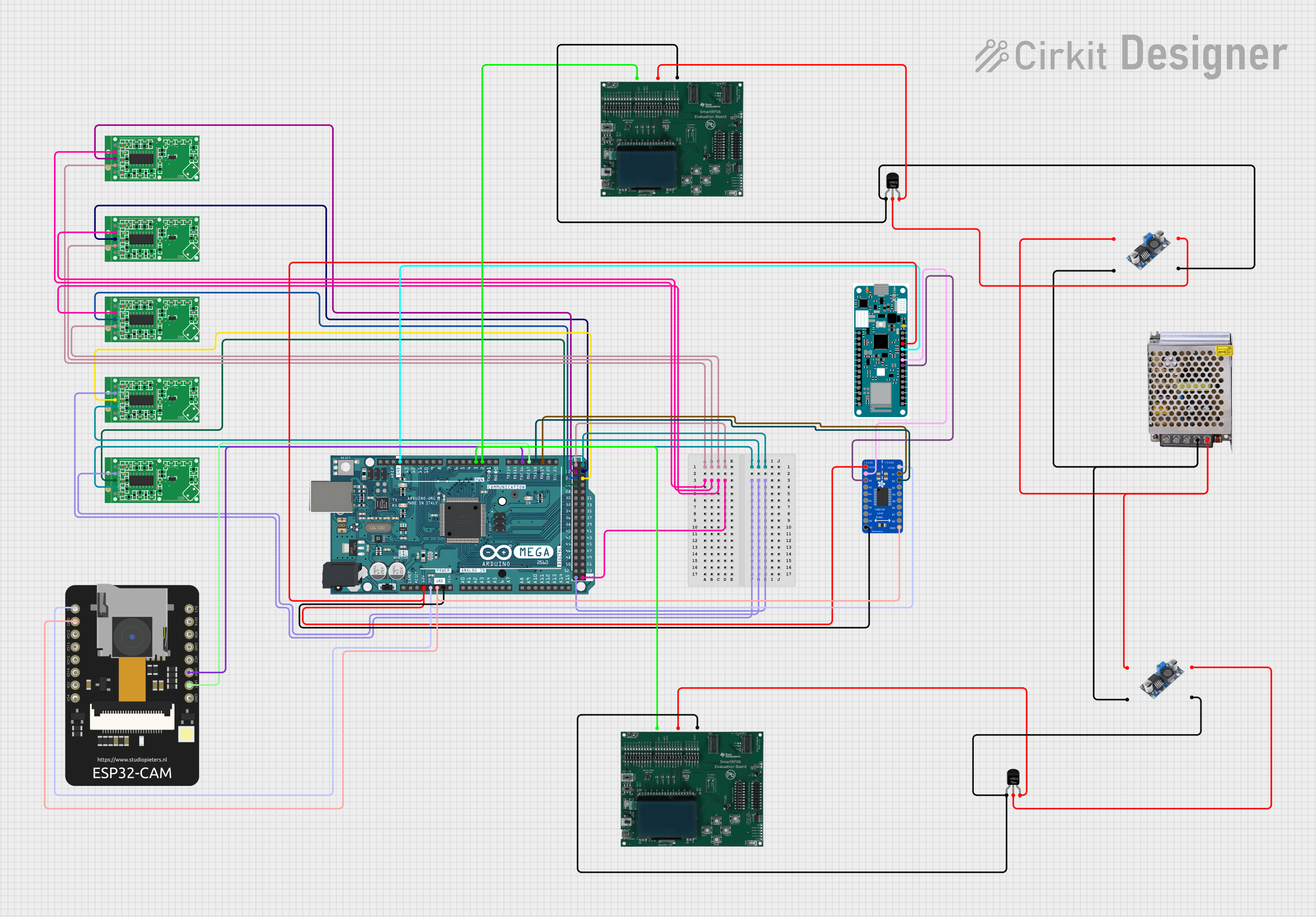
Arduino Mega 2560 and ESP32 CAM Based Motion Detection and RFID Security System

Circuit Documentation
Summary
This circuit integrates multiple components including motion sensor modules, microcontrollers, a logic level converter, an ESP32 CAM module, RFID boards, a power supply, and voltage regulators. The primary microcontrollers in the circuit are the Arduino Mega 2560 and the Arduino MKR WiFi 1010. The RCWL-0516 Microwave Radar Motion Sensor Modules are used for motion detection. The Adafruit TXB0108 is a bi-directional logic level converter that facilitates communication between devices operating at different voltage levels. The ESP32 CAM module is used for camera functionalities. RFID boards are included for identification purposes. The power supply and voltage regulators ensure that all components receive the correct operating voltages.
Component List
RCWL-0516 Microwave Radar Motion Sensor Module
- Pins: CDS, VIN, OUT, GND, 3V3
- Description: A motion detection sensor that uses microwave radar technology.
Arduino MKR WiFi 1010
- Pins: A0-A6, D0-D7, MOSI, SCK, MISO, SDA, SCL, RX, TX, RESET, GND, VCC, VIN, 5V
- Description: A microcontroller board with built-in Wi-Fi capability.
Adafruit TXB0108 8-channel Bi-directional Logic Level Converter
- Pins: VCCB, B1-B8, GND, OE, A1-A8, VCCA
- Description: A device that safely steps down 5V signals to 3.3V and steps up 3.3V to 5V at the same time.
ESP32 CAM
- Pins: 5V, GND, GPIO12-GPIO16, GPIO0, GPIO3 / RX, GPIO1 / TX, 3.3V / 5V / P_OUT
- Description: An ESP32-based board with support for camera interface and Wi-Fi.
Arduino Mega 2560
- Pins: IOREF, RESET, 3V3, 5V, GND, VIN, A0-A15, D0-D53, SDA, SCL, AREF
- Description: A microcontroller board based on the ATmega2560 with extensive I/O pins.
RFID Board
- Pins: RF2.3(Power), RF1.1(Ground), RF2.5(Output pin/Comms)
- Description: A board used for RFID communication.
POWER SUPPLY 12V 5AMP
- Pins: 220V Positive Pole (AC), 220V Negative Pole (AC), GND (DC), 12V-24V Output (DC)
- Description: A power supply unit that provides 12V, 5A DC output.
DC-DC 24V to 9V
- Pins: Vin+, Vin-, Vout+, Vout-
- Description: A DC-DC converter that steps down 24V to 9V.
Voltage Regulator
- Pins: GND, IN, OUT
- Description: A device that maintains a constant voltage level.
Wiring Details
RCWL-0516 Microwave Radar Motion Sensor Module
- VIN: Connected to 5V of Arduino Mega 2560.
- GND: Connected to GND of Arduino Mega 2560.
- OUT: Connected to digital pins D22-D26 of Arduino Mega 2560.
Arduino MKR WiFi 1010
- VCC: Connected to 3V3 of Arduino Mega 2560.
- GND: Connected to GND of Arduino Mega 2560.
- RX: Connected to A2 of Adafruit TXB0108.
- TX: Connected to A1 of Adafruit TXB0108.
Adafruit TXB0108 8-channel Bi-directional Logic Level Converter
- VCCA: Connected to 3V3 of Arduino Mega 2560.
- VCCB: Connected to 5V of ESP32 CAM and Arduino Mega 2560.
- GND: Connected to GND of ESP32 CAM and Arduino Mega 2560.
- OE: Connected to GND of Arduino Mega 2560.
- B1: Connected to D19/RX1 of Arduino Mega 2560.
- B2: Connected to D18/TX1 of Arduino Mega 2560.
- A1: Connected to TX of Arduino MKR WiFi 1010.
- A2: Connected to RX of Arduino MKR WiFi 1010.
ESP32 CAM
- 5V: Connected to 5V of Arduino Mega 2560.
- GND: Connected to GND of Arduino Mega 2560.
- GPIO1 / TX: Connected to D17 PWM/RX2 of Arduino Mega 2560.
- GPIO3 / RX: Connected to D16 PWM/TX2 of Arduino Mega 2560.
RFID Board
- RF2.3(Power): Connected to OUT of Voltage Regulator.
- RF1.1(Ground): Connected to GND of Voltage Regulator and Vout- of DC-DC 24V to 9V.
- RF2.5(Output pin/Comms): Connected to D2 PWM and D3 PWM of Arduino Mega 2560.
POWER SUPPLY 12V 5AMP
- GND (DC): Connected to Vin- of both DC-DC 24V to 9V converters.
- 12V-24V Output (DC): Connected to Vin+ of both DC-DC 24V to 9V converters.
DC-DC 24V to 9V
- Vin+: Connected to 12V-24V Output (DC) of POWER SUPPLY 12V 5AMP.
- Vin-: Connected to GND (DC) of POWER SUPPLY 12V 5AMP.
- Vout+: Connected to IN of Voltage Regulators.
- Vout-: Connected to GND of Voltage Regulators and RFID Boards.
Voltage Regulator
- IN: Connected to Vout+ of DC-DC 24V to 9V.
- GND: Connected to Vout- of DC-DC 24V to 9V and RF1.1(Ground) of RFID Boards.
- OUT: Connected to RF2.3(Power) of RFID Boards.
Documented Code
Arduino Mega 2560 Code (sketch.ino)
void setup() {
  // put your setup code here, to run once:

}

void loop() {
  // put your main code here, to run repeatedly:

}
Note: The provided code for the Arduino Mega 2560 is a template with empty setup and loop functions. This code needs to be populated with the logic required for the circuit's operation.