
Wi-Fi Controlled Weather Station with OLED Display and Buzzer
View and Edit Project In Cirkit Designer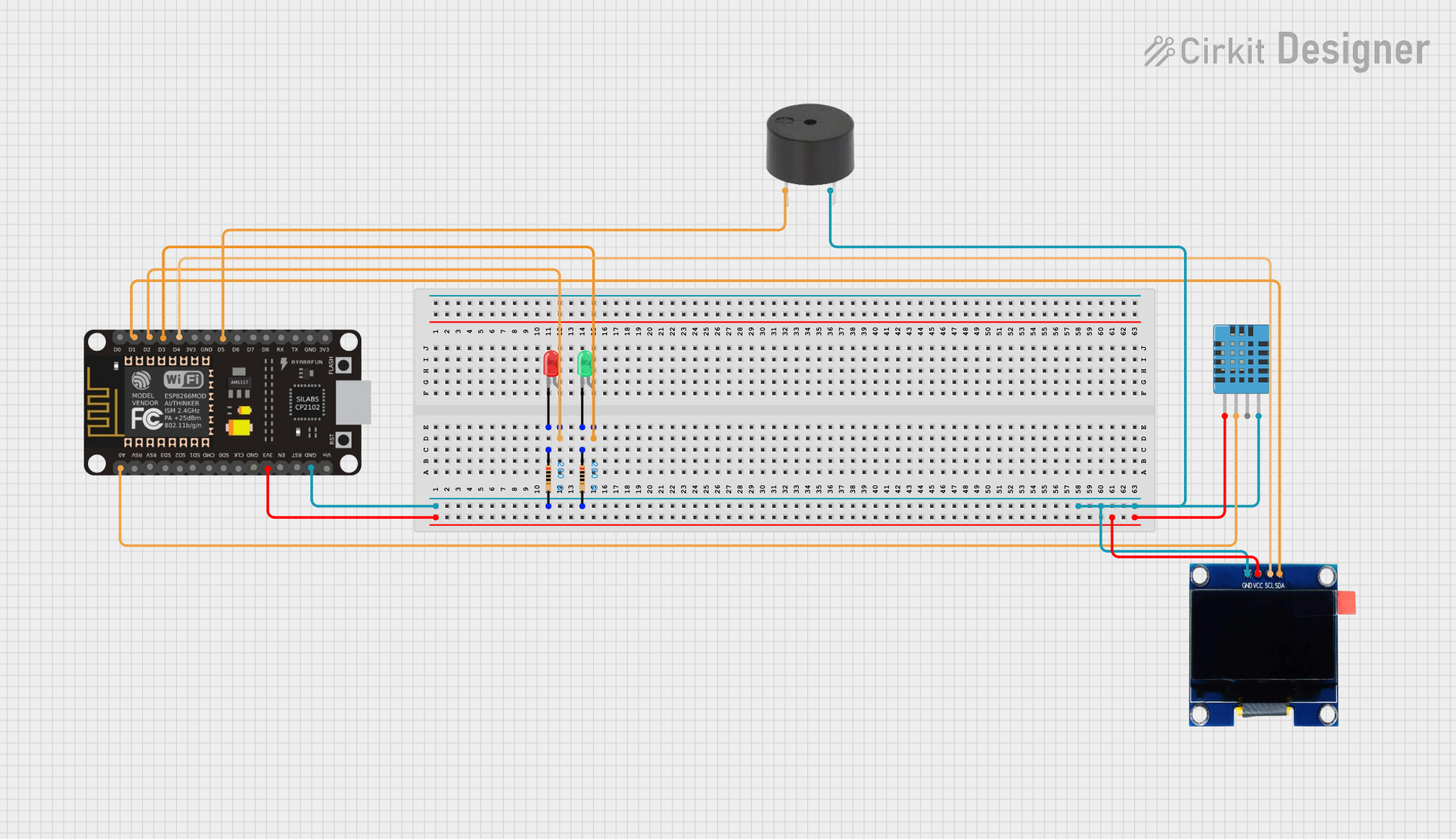
Circuit Documentation
Summary
This circuit is designed to monitor temperature and humidity using a DHT11 sensor, display the readings on an OLED screen, and provide visual and auditory alerts using LEDs and a buzzer. The circuit is controlled by an ESP8266 NodeMCU microcontroller.
Component List
DHT11 Humidity and Temperature Sensor
- Pins: VDD, DATA, NULL, GND
- Description: Measures temperature and humidity.
Buzzer
- Pins: PIN, GND
- Description: Provides auditory alerts.
OLED 1.3" Display
- Pins: GND, VCC, SCL, SDA
- Description: Displays temperature and humidity readings.
LED: Two Pin (Red)
- Pins: Cathode, Anode
- Description: Provides visual alerts.
LED: Two Pin (Green)
- Pins: Cathode, Anode
- Description: Provides visual alerts.
Resistor (200 Ohms)
- Pins: Pin1, Pin2
- Description: Limits current to LEDs.
ESP8266 NodeMCU
- Pins: D0, D1, D2, D3, D4, 3V3, GND, D5, D6, D7, D8, RX, TX, A0, RSV, SD3, SD2, SD1, CMD, SD0, CLK, EN, RST, VIN
- Description: Microcontroller that controls the circuit.
Wiring Details
DHT11 Humidity and Temperature Sensor
- VDD connected to 3V3 of ESP8266 NodeMCU
- DATA connected to A0 of ESP8266 NodeMCU
- GND connected to GND of ESP8266 NodeMCU
Buzzer
- PIN connected to D5 of ESP8266 NodeMCU
- GND connected to GND of ESP8266 NodeMCU
OLED 1.3" Display
- VCC connected to 3V3 of ESP8266 NodeMCU
- GND connected to GND of ESP8266 NodeMCU
- SDA connected to D1 of ESP8266 NodeMCU
- SCL connected to D4 of ESP8266 NodeMCU
LED: Two Pin (Red)
- Anode connected to D2 of ESP8266 NodeMCU
- Cathode connected to Pin1 of Resistor (200 Ohms)
- Pin2 of Resistor (200 Ohms) connected to GND of ESP8266 NodeMCU
LED: Two Pin (Green)
- Anode connected to D3 of ESP8266 NodeMCU
- Cathode connected to Pin1 of Resistor (200 Ohms)
- Pin2 of Resistor (200 Ohms) connected to GND of ESP8266 NodeMCU
ESP8266 NodeMCU
- 3V3 connected to VCC of OLED 1.3" Display and VDD of DHT11 Sensor
- GND connected to GND of OLED 1.3" Display, DHT11 Sensor, Buzzer, and both Resistors
- D1 connected to SDA of OLED 1.3" Display
- D2 connected to Anode of Red LED
- D3 connected to Anode of Green LED
- D4 connected to SCL of OLED 1.3" Display
- D5 connected to PIN of Buzzer
- A0 connected to DATA of DHT11 Sensor
Code
No code provided.