
Arduino Nano-Based Smart Home Automation System with Motion and IR Sensors
View and Edit Project In Cirkit Designer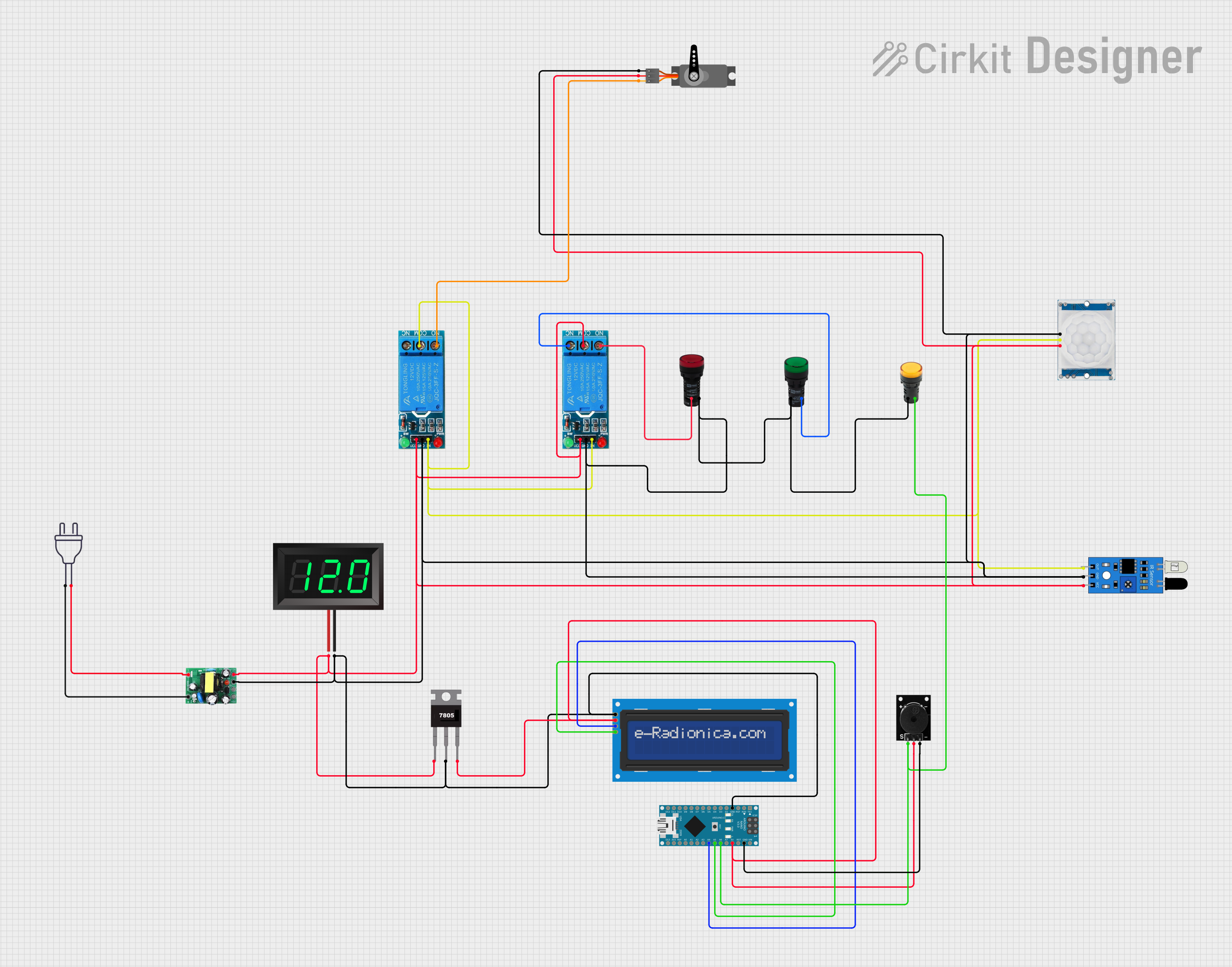
Circuit Documentation
Summary
This circuit integrates various sensors, actuators, and display components controlled by an Arduino Nano. The circuit includes a servo motor, a relay module, a PIR motion sensor, an IR sensor, an LCD screen, a voltmeter, a passive buzzer, and pilot lamps. The power supply is managed by an AC-DC PSU board converting 220V AC to 5V and 12V DC.
Component List
Servo
- Pins: GND, VCC, PWM
- Description: A motor that can be controlled to move to a specific position.
- Purpose: Used for precise control of angular position.
12V SINGLE CHANNEL RELAY
- Pins: NC, COM, NO, IN, GND, VCC
- Description: A relay module for switching high voltage devices.
- Purpose: Used to control high voltage devices with low voltage signals.
HC-SR501 PIR motion sensor
- Pins: Output, Ground, Power Supply
- Description: A sensor that detects motion by measuring infrared light.
- Purpose: Used for motion detection.
IR Sensor
- Pins: out, gnd, vcc
- Description: An infrared sensor for detecting objects.
- Purpose: Used for object detection.
AC-DC PSU board 220V-5V&12V
- Pins: AC-N, AC-L, +5V, GND, +12V
- Description: A power supply unit converting 220V AC to 5V and 12V DC.
- Purpose: Provides power to the circuit components.
Power 220V
- Pins: hot wire, neutral wire
- Description: Standard 220V AC power source.
- Purpose: Supplies AC power to the PSU board.
LCD screen 16x2 I2C
- Pins: SCL, SDA, VCC, GND
- Description: A 16x2 character LCD display with I2C interface.
- Purpose: Used for displaying information.
Arduino Nano
- Pins: D1/TX, D0/RX, RESET, GND, D2, D3, D4, D5, D6, D7, D8, D9, D10, D11/MOSI, D12/MISO, VIN, 5V, A7, A6, A5, A4, A3, A2, A1, A0, AREF, 3V3, D13/SCK
- Description: A small, complete, and breadboard-friendly microcontroller board.
- Purpose: Controls the circuit components.
7-Segment Panel Voltmeter
- Pins: V+, V-
- Description: A voltmeter for measuring voltage.
- Purpose: Displays the voltage level.
7805
- Pins: Vin, Gnd, Vout
- Description: A voltage regulator that outputs 5V.
- Purpose: Provides a stable 5V output.
Passive Buzzer
- Pins: S output signal, +VCC, GND
- Description: A buzzer that produces sound when a signal is applied.
- Purpose: Used for audio alerts.
Pilot Lamp Green
- Pins: X1, X2
- Description: A green indicator lamp.
- Purpose: Indicates status.
Pilot LED Yellow
- Pins: G, +
- Description: A yellow LED indicator.
- Purpose: Indicates status.
Pilot Lamp Red
- Pins: X1, X2
- Description: A red indicator lamp.
- Purpose: Indicates status.
Wiring Details
Servo
- GND connected to GND of the circuit.
- VCC connected to VCC of the circuit.
- PWM connected to NO of the 12V SINGLE CHANNEL RELAY.
12V SINGLE CHANNEL RELAY
- NC connected to X2 of the Pilot Lamp Green.
- COM connected to out of the IR sensor.
- NO connected to PWM of the Servo.
- IN connected to Output of the HC-SR501 PIR motion sensor and IN of the other 12V SINGLE CHANNEL RELAY.
- GND connected to GND of the circuit.
- VCC connected to +12V of the AC-DC PSU board.
HC-SR501 PIR motion sensor
- Output connected to IN of the 12V SINGLE CHANNEL RELAY.
- Ground connected to GND of the circuit.
- Power Supply connected to +12V of the AC-DC PSU board.
IR Sensor
- out connected to COM of the 12V SINGLE CHANNEL RELAY.
- gnd connected to GND of the circuit.
- vcc connected to VCC of the circuit.
AC-DC PSU board 220V-5V&12V
- AC-N connected to hot wire of the power 220V.
- AC-L connected to neutral wire of the power 220V.
- +5V connected to VCC of the LCD screen 16x2 I2C, Passive Buzzer, and 5V of the Arduino Nano.
- GND connected to GND of the circuit.
- +12V connected to VCC of the 12V SINGLE CHANNEL RELAY and Power Supply of the HC-SR501 PIR motion sensor.
Power 220V
- hot wire connected to AC-N of the AC-DC PSU board.
- neutral wire connected to AC-L of the AC-DC PSU board.
LCD screen 16x2 I2C
- SCL connected to A5 of the Arduino Nano.
- SDA connected to A4 of the Arduino Nano.
- VCC connected to +5V of the AC-DC PSU board.
- GND connected to GND of the circuit.
Arduino Nano
- GND connected to GND of the circuit.
- 5V connected to +5V of the AC-DC PSU board.
- A5 connected to SCL of the LCD screen 16x2 I2C.
- A4 connected to SDA of the LCD screen 16x2 I2C.
- A6 connected to S output signal of the Passive Buzzer.
7-Segment Panel Voltmeter
- V+ connected to VCC of the circuit.
- V- connected to GND of the circuit.
7805
- Vin connected to VCC of the circuit.
- Gnd connected to GND of the circuit.
- Vout connected to VCC of the LCD screen 16x2 I2C, Passive Buzzer, and 5V of the Arduino Nano.
Passive Buzzer
- S output signal connected to A6 of the Arduino Nano.
- +VCC connected to VCC of the circuit.
- GND connected to GND of the circuit.
Pilot Lamp Green
- X1 connected to GND of the circuit.
- X2 connected to NC of the 12V SINGLE CHANNEL RELAY.
Pilot LED Yellow
- G connected to GND of the circuit.
- + connected to S output signal of the Passive Buzzer.
Pilot Lamp Red
- X1 connected to NO of the 12V SINGLE CHANNEL RELAY.
- X2 connected to GND of the circuit.
Documented Code
Arduino Nano Code
void setup() {
  // put your setup code here, to run once:

}

void loop() {
  // put your main code here, to run repeatedly:

}
Servo Code
void setup() {
  // put your setup code here, to run once:

}

void loop() {
  // put your main code here, to run repeatedly:

}
This documentation provides a comprehensive overview of the circuit, including a summary, detailed component list, wiring details, and documented code for the microcontrollers.