Cirkit Designer
Your all-in-one circuit design IDE
Home /
Project Documentation
ESP32-Based Weather Station with SD Card Logging and I2C Display
Circuit Documentation
Summary
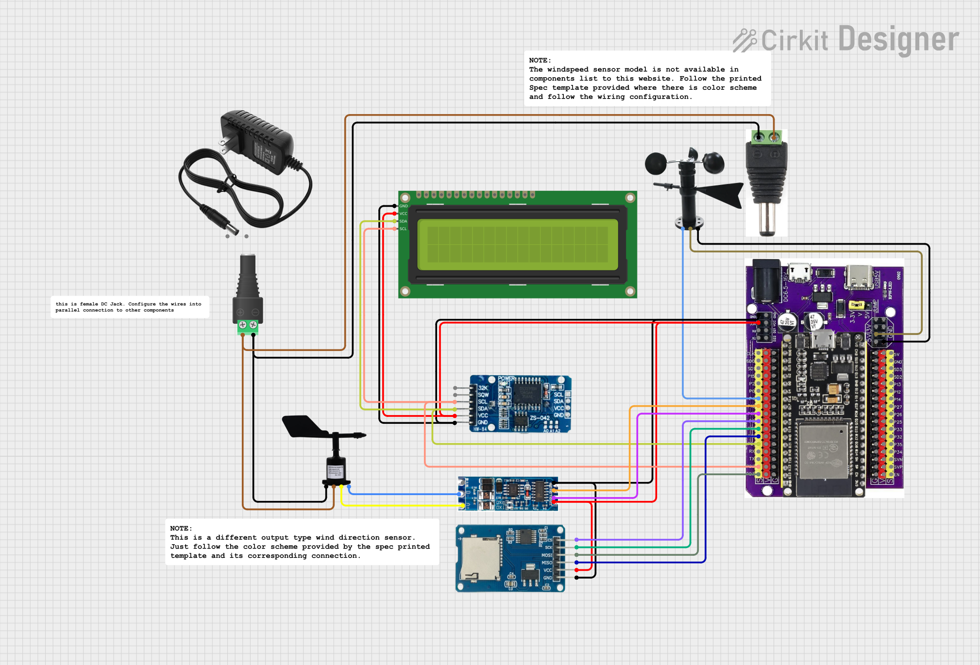
This circuit is designed to interface an ESP32 microcontroller with various sensors and modules, including a Micro SD Card Module, Wind Direction Sensor, RTC DS3231, Wind Vane, 16x2 I2C LCD, and a UART TTL to RS485 Two-way Converter. The circuit also includes a 12V power supply and connectors for power distribution. The ESP32 handles data acquisition, storage, and communication with the connected peripherals.
Component List
Micro SD Card Module
- Description: A module for interfacing with micro SD cards.
- Pins: cs, sck, mosi, miso, vcc, gnd
Wind Direction Sensor
- Description: A sensor for measuring wind direction.
- Pins: GND, VIN, NC, Data
Esp32 on Baseboard
- Description: A development board featuring the ESP32 microcontroller.
- Pins: GPIO23, GPIO22, GPIO1/TX, GPIO3/RX, GPIO21, GPIO19, GPIO18, GPIO5, GPIO17, GPIO16, GPIO4, GPIO0, GPIO2, GPIO15, SD1, SD0, CLK, V, G, GPIO36, GPIO39, GPIO34, GPIO35, GPIO32, GPIO33, GPIO25, GPIO26, GPIO27, GPIO14, GPIO12, GPIO13, SD2, SD3, GND, 5V, 3V, TX, RX, VCC, D22, D21
UART TTL to RS485 Two-way Converter
- Description: A module for converting UART TTL signals to RS485.
- Pins: VCC, TXD, RXD, GND, A, B
RTC DS3231
- Description: A real-time clock module.
- Pins: 32K, SQW, SCL, SDA, VCC, GND
Wind Vane
- Description: A sensor for measuring wind speed.
- Pins: A0, VCC, GND
16x2 I2C LCD
- Description: A 16x2 character LCD with I2C interface.
- Pins: GND, VCC, SDA, SCL
12V Power Supply
- Description: A power supply providing 12V output.
- Pins: +, -
2.1mm Male Connector
- Description: A 2.1mm male power connector.
- Pins: +, -
2.1mm Barrel Jack with Terminal Block
- Description: A 2.1mm barrel jack with terminal block for power connections.
- Pins: POS, NEG
Wiring Details
Micro SD Card Module
- cs connected to GPIO5 of Esp32 on Baseboard
- sck connected to GPIO18 of Esp32 on Baseboard
- mosi connected to GPIO23 of Esp32 on Baseboard
- miso connected to GPIO19 of Esp32 on Baseboard
- vcc connected to VCC of Esp32 on Baseboard
- gnd connected to GND of Esp32 on Baseboard
Wind Direction Sensor
- GND connected to NEG of 2.1mm Barrel Jack with Terminal Block
- VIN connected to POS of 2.1mm Barrel Jack with Terminal Block
- NC connected to A of UART TTL to RS485 Two-way Converter
- Data connected to B of UART TTL to RS485 Two-way Converter
Esp32 on Baseboard
- GPIO23 connected to mosi of Micro SD Card Module
- GPIO22 connected to SCL of RTC DS3231 and 16x2 I2C LCD
- GPIO21 connected to SDA of RTC DS3231 and 16x2 I2C LCD
- GPIO19 connected to miso of Micro SD Card Module
- GPIO18 connected to sck of Micro SD Card Module
- GPIO5 connected to cs of Micro SD Card Module
- GPIO17 connected to TXD of UART TTL to RS485 Two-way Converter
- GPIO16 connected to RXD of UART TTL to RS485 Two-way Converter
- GPIO4 connected to A0 of Wind Vane
- GND connected to GND of Wind Vane, RTC DS3231, 16x2 I2C LCD, UART TTL to RS485 Two-way Converter, and Micro SD Card Module
- 5V connected to VCC of Wind Vane
- VCC connected to VCC of RTC DS3231, 16x2 I2C LCD, UART TTL to RS485 Two-way Converter, and Micro SD Card Module
UART TTL to RS485 Two-way Converter
- TXD connected to GPIO17 of Esp32 on Baseboard
- RXD connected to GPIO16 of Esp32 on Baseboard
- VCC connected to VCC of Esp32 on Baseboard
- GND connected to GND of Esp32 on Baseboard
- A connected to NC of Wind Direction Sensor
- B connected to Data of Wind Direction Sensor
RTC DS3231
- SCL connected to GPIO22 of Esp32 on Baseboard
- SDA connected to GPIO21 of Esp32 on Baseboard
- VCC connected to VCC of Esp32 on Baseboard
- GND connected to GND of Esp32 on Baseboard
Wind Vane
- A0 connected to GPIO4 of Esp32 on Baseboard
- VCC connected to 5V of Esp32 on Baseboard
- GND connected to GND of Esp32 on Baseboard
16x2 I2C LCD
- SCL connected to GPIO22 of Esp32 on Baseboard
- SDA connected to GPIO21 of Esp32 on Baseboard
- VCC connected to VCC of Esp32 on Baseboard
- GND connected to GND of Esp32 on Baseboard
12V Power Supply
- + connected to POS of 2.1mm Barrel Jack with Terminal Block
- - connected to NEG of 2.1mm Barrel Jack with Terminal Block
2.1mm Male Connector
- + connected to POS of 2.1mm Barrel Jack with Terminal Block
- - connected to NEG of 2.1mm Barrel Jack with Terminal Block
2.1mm Barrel Jack with Terminal Block
- POS connected to + of 2.1mm Male Connector and VIN of Wind Direction Sensor
- NEG connected to - of 2.1mm Male Connector and GND of Wind Direction Sensor
Documented Code
void setup() {
  // put your setup code here, to run once:

}

void loop() {
  // put your main code here, to run repeatedly:

}
/*
Note:
GPIO Pin Assignments:
- 21 and 22: I2C bus for RTC module (0x68) and 16x2 LCD (0x27)
- 16 and 17: UART to RS485 module (RX, TX respectively)
- 4: NPNR output windspeed
- 19, 23, 18, 5: SD card module (MISO, MOSI, SCK, CS respectively)
- 21 and 22: EEPROM (0x57)
*/
This documentation provides a comprehensive overview of the circuit, including a summary, detailed component list, wiring details, and documented code.