Arduino-Controlled Dual DC Motor Driver with Directional Pushbutton Interface
Circuit Documentation
Summary
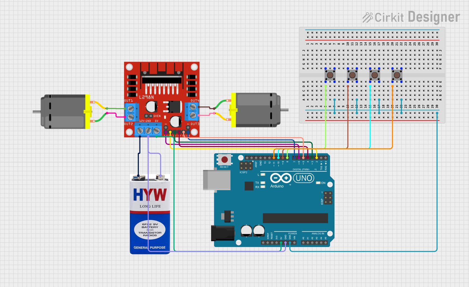
This circuit is designed to control two DC motors using an L298N DC motor driver module, which is interfaced with an Arduino UNO microcontroller. The circuit includes pushbuttons for directional control of the motors, allowing for forward, backward, left, and right movements. A 9V battery provides the power source for the motor driver, while the Arduino UNO is powered through its 5V pin connected to the motor driver's 5V output.
Component List
L298N DC Motor Driver
- Description: A module used to control the speed and direction of two DC motors.
- Pins: OUT1, OUT2, 12V, GND, 5V, OUT3, OUT4, 5V-ENA-JMP-I, 5V-ENA-JMP-O, +5V-J1, +5V-J2, ENA, IN1, IN2, IN3, IN4, ENB
Arduino UNO
- Description: A microcontroller board based on the ATmega328P, used for controlling the logic of the circuit.
- Pins: UNUSED, IOREF, Reset, 3.3V, 5V, GND, Vin, A0, A1, A2, A3, A4, A5, SCL, SDA, AREF, D13, D12, D11, D10, D9, D8, D7, D6, D5, D4, D3, D2, D1, D0
DC Motor (x2)
- Description: Electric motors that convert electrical energy into mechanical motion.
- Pins: pin 1, pin 2
9V Battery
- Description: A power source for the motor driver.
- Pins: +, -
Pushbutton (x4)
- Description: A simple switch mechanism for controlling some aspect of a machine or a process.
- Pins: Pin 3 (out), Pin 4 (out), Pin 1 (in), Pin 2 (in)
Wiring Details
L298N DC Motor Driver
- OUT1: Connected to DC Motor 1 pin 2
- OUT2: Connected to DC Motor 1 pin 1
- 12V: Connected to 9V battery +
- GND: Connected to 9V battery - and Arduino UNO GND
- 5V: Connected to Arduino UNO 5V
- OUT3: Connected to DC Motor 2 pin 2
- OUT4: Connected to DC Motor 2 pin 1
- ENA: Connected to Arduino UNO D6
- IN1: Connected to Arduino UNO D2
- IN2: Connected to Arduino UNO D3
- IN3: Connected to Arduino UNO D4
- IN4: Connected to Arduino UNO D5
- ENB: Connected to Arduino UNO D7
Arduino UNO
- GND: Connected to L298N GND and all Pushbutton Pin 4 (out)
- 5V: Connected to L298N 5V
- D6: Connected to L298N ENA
- D2: Connected to L298N IN1
- D3: Connected to L298N IN2
- D4: Connected to L298N IN3
- D5: Connected to L298N IN4
- D7: Connected to L298N ENB
- D8: Connected to Pushbutton 1 Pin 2 (in)
- D9: Connected to Pushbutton 2 Pin 2 (in)
- D10: Connected to Pushbutton 3 Pin 2 (in)
- D11: Connected to Pushbutton 4 Pin 2 (in)
DC Motors
- DC Motor 1 pin 1: Connected to L298N OUT2
- DC Motor 1 pin 2: Connected to L298N OUT1
- DC Motor 2 pin 1: Connected to L298N OUT4
- DC Motor 2 pin 2: Connected to L298N OUT3
9V Battery
- +: Connected to L298N 12V
- -: Connected to L298N GND
Pushbuttons
- Pushbutton 1 Pin 2 (in): Connected to Arduino UNO D8
- Pushbutton 2 Pin 2 (in): Connected to Arduino UNO D9
- Pushbutton 3 Pin 2 (in): Connected to Arduino UNO D10
- Pushbutton 4 Pin 2 (in): Connected to Arduino UNO D11
- All Pushbutton Pin 4 (out): Connected to Arduino UNO GND
Documented Code
// Define pins for L298N connections
const int ENA = 6; // Enable pin for Motor A
const int IN1 = 2; // Input 1 for Motor A
const int IN2 = 3; // Input 2 for Motor A
const int IN3 = 4; // Input 1 for Motor B
const int IN4 = 5; // Input 2 for Motor B
const int ENB = 7; // Enable pin for Motor B

// Define pins for push buttons
const int forwardButton = 8;
const int backwardButton = 9;
const int leftButton = 10;
const int rightButton = 11;

void setup() {
  // Set motor control pins as output
  pinMode(ENA, OUTPUT);
  pinMode(IN1, OUTPUT);
  pinMode(IN2, OUTPUT);
  pinMode(IN3, OUTPUT);
  pinMode(IN4, OUTPUT);
  pinMode(ENB, OUTPUT);

  // Set button pins as input with pull-up resistors
  pinMode(forwardButton, INPUT_PULLUP);
  pinMode(backwardButton, INPUT_PULLUP);
  pinMode(leftButton, INPUT_PULLUP);
  pinMode(rightButton, INPUT_PULLUP);
}

void loop() {
  // Read the state of each button
  bool forward = digitalRead(forwardButton) == LOW;
  bool backward = digitalRead(backwardButton) == LOW;
  bool left = digitalRead(leftButton) == LOW;
  bool right = digitalRead(rightButton) == LOW;

  // Forward
  if (forward) {
    digitalWrite(IN1, HIGH);
    digitalWrite(IN2, LOW);
    digitalWrite(IN3, HIGH);
    digitalWrite(IN4, LOW);
    analogWrite(ENA, 255); // Full speed
    analogWrite(ENB, 255); // Full speed
  }
  // Backward
  else if (backward) {
    digitalWrite(IN1, LOW);
    digitalWrite(IN2, HIGH);
    digitalWrite(IN3, LOW);
    digitalWrite(IN4, HIGH);
    analogWrite(ENA, 255);
    analogWrite(ENB, 255);
  }
  // Left
  else if (left) {
    digitalWrite(IN1, LOW);
    digitalWrite(IN2, HIGH);
    digitalWrite(IN3, HIGH);
    digitalWrite(IN4, LOW);
    analogWrite(ENA, 255);
    analogWrite(ENB, 255);
  }
  // Right
  else if (right) {
    digitalWrite(IN1, HIGH);
    digitalWrite(IN2, LOW);
    digitalWrite(IN3, LOW);
    digitalWrite(IN4, HIGH);
    analogWrite(ENA, 255);
    analogWrite(ENB, 255);
  }
  // Stop if no buttons are pressed
  else {
    digitalWrite(IN1, LOW);
    digitalWrite(IN2, LOW);
    digitalWrite(IN3, LOW);
    digitalWrite(IN4, LOW);
    analogWrite(ENA, 0);
    analogWrite(ENB, 0);
  }
}
This code is designed to run on the Arduino UNO microcontroller. It sets up the pins connected to the L298N motor driver and the pushbuttons. In the loop function, it reads the state of the pushbuttons and controls the motors accordingly. The motors can be driven forward, backward, turned left, or right based on the button pressed. If no buttons are pressed, the motors are stopped.