Cirkit Designer
Your all-in-one circuit design IDE
Home /
Project Documentation
Arduino UNO-Based Environmental Monitoring System with Wi-Fi and GSM Control
Circuit Documentation
Summary
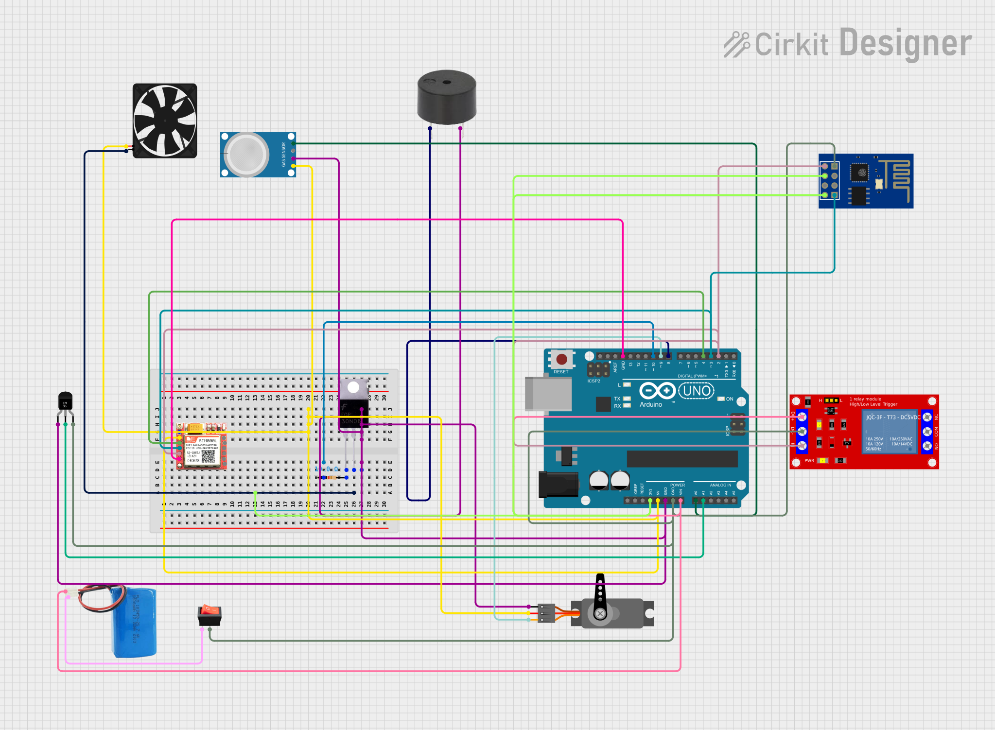
This document provides a detailed overview of a circuit that includes a variety of components such as an Arduino UNO, a servo motor, a buzzer, an MQ-4 gas sensor, a resistor, an LM35 temperature sensor, a SIM800L GSM module, a 5V relay module, a fan, a MOSFET, an ESP8266 ESP-01 WiFi module, a 5V battery, and a rocker switch. The circuit is designed to interface with sensors, actuators, communication modules, and power management components. The Arduino UNO serves as the central microcontroller unit, orchestrating the interactions between the various components.
Component List
Arduino UNO
- Microcontroller board based on the ATmega328P
- Pins: UNUSED, IOREF, Reset, 3.3V, 5V, GND, Vin, A0-A5, SCL, SDA, AREF, D0-D13
Servo
- A motor capable of precise position control
- Pins: GND, VCC, PWM
Buzzer
- An electromechanical component that produces sound
- Pins: PIN, GND
MQ-4 Gas Sensor
- A sensor for detecting natural gas and methane levels
- Pins: A0, D0, GND, VCC
Resistor (10 Ohms)
- A passive two-terminal electrical component that implements electrical resistance
- Pins: pin1, pin2
Temperature Sensor (LM35)
- A precision integrated-circuit temperature sensor
- Pins: +Vs, Vout, GND
SIM800L GSM Module
- A complete Quad-band GSM/GPRS solution for cellular communication
- Pins: NFT, RING, VCC, DTR, RST, MIC+, RXD, MIC-, TXD, SPK+, GND, SPK-
1 Channel 5V Relay Module
- An electrically operated switch that allows you to turn on or off a circuit using voltage and/or current much higher than a microcontroller could handle
- Pins: VCC+, VCC- (GND), IN, N.O., COM, N.C.
Fan
- An electric device that creates airflow
- Pins: GND, 5V
MOSFET
- A type of field-effect transistor used for amplifying or switching electronic signals
- Pins: Gate, Drain, Source
ESP8266 ESP-01 WiFi Module
- A self-contained SOC with integrated TCP/IP protocol stack that can give any microcontroller access to a WiFi network
- Pins: TXD, CH_PD, RST, VCC, GND, GPIO_2, GPIO_0, RXD
5V Battery
- A power source providing a 5V output
- Pins: positive, negative
Rocker Switch
- An on-off switch that rocks (rather than trips) when pressed
- Pins: output, input
Wiring Details
Arduino UNO
- 3.3V connected to ESP8266 ESP-01 WiFi Module's CH_PD and VCC
- 5V connected to Servo's VCC, SIM800L's VCC, Fan's 5V, and MQ-4's VCC
- GND connected to Servo's GND, Temperature Sensor (LM35)'s GND, Buzzer's GND, MQ-4's GND, and common ground with Rocker Switch
- Vin connected to 1 Channel 5V Relay Module's VCC+ and 5V Battery's positive
- A0 connected to MQ-4's A0
- A1 connected to Temperature Sensor (LM35)'s Vout
- D10 connected to Resistor's pin1
- D9 connected to Servo's PWM
- D8 connected to Buzzer's PIN
- D4 connected to SIM800L's RST
- D3 connected to SIM800L's RXD and ESP8266 ESP-01 WiFi Module's RXD
- D2 connected to SIM800L's TXD, ESP8266 ESP-01 WiFi Module's TXD, and 1 Channel 5V Relay Module's IN
Servo
- GND connected to common ground
- VCC connected to Arduino UNO's 5V
- PWM connected to Arduino UNO's D9
Buzzer
- GND connected to common ground
- PIN connected to Arduino UNO's D8
MQ-4 Gas Sensor
- A0 connected to Arduino UNO's A0
- D0 not connected
- GND connected to common ground
- VCC connected to Arduino UNO's 5V
Resistor (10 Ohms)
- pin1 connected to Arduino UNO's D10
- pin2 connected to MOSFET's Gate
Temperature Sensor (LM35)
- +Vs connected to common ground
- Vout connected to Arduino UNO's A1
- GND connected to common ground
SIM800L GSM Module
- GND connected to common ground
- VCC connected to Arduino UNO's 5V
- RST connected to Arduino UNO's D4
- RXD connected to Arduino UNO's D3
- TXD connected to Arduino UNO's D2
1 Channel 5V Relay Module
- VCC+ connected to Arduino UNO's Vin
- VCC- (GND) connected to common ground
- IN connected to Arduino UNO's D2
Fan
- GND connected to MOSFET's Drain
- 5V connected to Arduino UNO's 5V
MOSFET
- Gate connected to Resistor's pin2
- Drain connected to Fan's GND
- Source connected to common ground
ESP8266 ESP-01 WiFi Module
- TXD connected to Arduino UNO's D2
- CH_PD connected to Arduino UNO's 3.3V
- RST not connected
- VCC connected to Arduino UNO's 3.3V
- GND connected to common ground
- GPIO_2 not connected
- GPIO_0 not connected
- RXD connected to Arduino UNO's D3
5V Battery
- positive connected to Arduino UNO's Vin
- negative connected to Rocker Switch's input
Rocker Switch
- output connected to common ground
- input connected to 5V Battery's negative
Documented Code
Arduino UNO Code (sketch.ino)
void setup() {
  // put your setup code here, to run once:

}

void loop() {
  // put your main code here, to run repeatedly:

}
Additional Notes (documentation.txt)
No additional code documentation provided.