
Arduino Nano-Controlled Smart Irrigation System with Environmental Monitoring
View and Edit Project In Cirkit Designer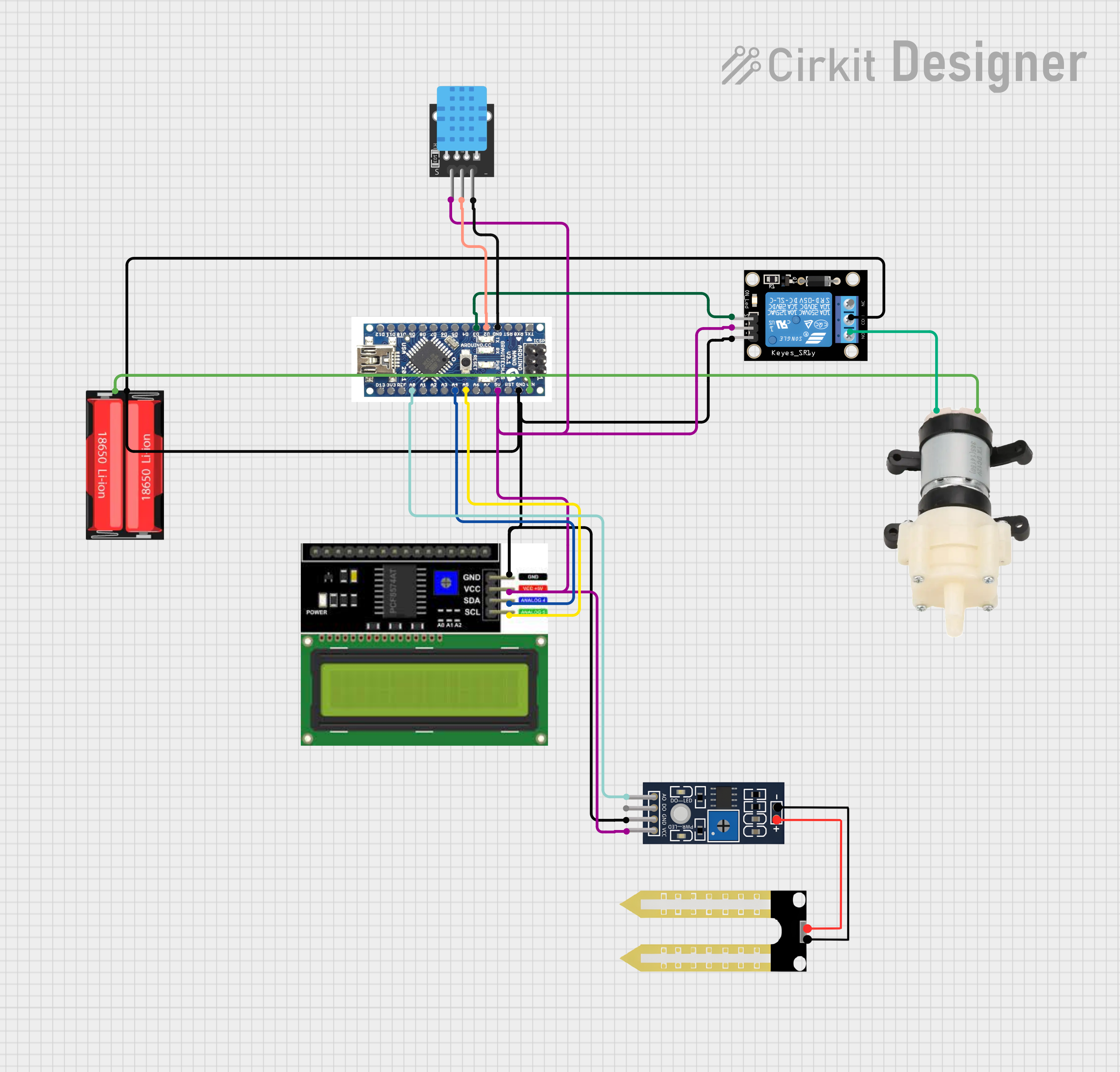
Circuit Documentation
Summary
This circuit integrates various components controlled by an Arduino Nano microcontroller to perform a set of functions that likely involve environmental sensing, data display, and control of a water pump. The DHT11 sensor is used for measuring temperature and humidity, while the Humidity YL-69 sensor is likely used for soil moisture detection. The LCD I2C Display provides a user interface for displaying data. A relay module is used to control a Mini Diaphragm Water Pump, and the entire system is powered by an 18650 Li-Ion battery.
Component List
Arduino Nano
- Microcontroller board based on the ATmega328P
- It has a variety of digital and analog I/O pins.
Relay Module 1 Channel
- An electrically operated switch that allows you to control a high power circuit with a low power signal.
- It has a single channel which can be used to turn on/off devices like motors or lights.
DHT11
- A basic, ultra low-cost digital temperature and humidity sensor.
- It uses a capacitive humidity sensor and a thermistor to measure the surrounding air.
LCD I2C Display
- A liquid crystal display that uses the I2C communication protocol.
- It is typically used to display information to the user.
Humidity YL-69
- A sensor used to measure the moisture content in soil.
- It can be used in automatic watering systems for plants.
Mini Diaphragm Water Pump
- A small electric pump used to move water or other fluids.
- It is commonly used in DIY projects for liquid transfer.
18650 Li-Ion Battery
- A rechargeable battery commonly used in laptops, flashlights, and electric vehicles.
- It provides a power source for portable electronics.
Wiring Details
Arduino Nano
- Digital Pins:
- D2: Connected to DHT11 (Signal)
- D3: Connected to Relay Module (Signal)
- Analog Pins:
- A0: Connected to Humidity YL-69 (Analog Output)
- A4: Connected to LCD I2C Display (SDA)
- A5: Connected to LCD I2C Display (SCL)
- Power Pins:
- 5V: Connected to Relay Module, LCD I2C Display, Humidity YL-69, DHT11 (5V Power)
- GND: Common ground with all components
- VIN: Connected to 18650 Li-Ion Battery (Positive)
Relay Module 1 Channel
- Signal (S): Connected to Arduino Nano (D3)
- Power (5V): Connected to Arduino Nano (5V)
- Ground (GND): Common ground with all components
- Normally Open (NO): Connected to Mini Diaphragm Water Pump (Negative)
- Common (COM): Connected to ground
DHT11
- Signal (S): Connected to Arduino Nano (D2)
- Power (5V): Connected to Arduino Nano (5V)
- Ground (GND): Common ground with all components
LCD I2C Display
- SDA: Connected to Arduino Nano (A4)
- SCL: Connected to Arduino Nano (A5)
- Power (VCC): Connected to Arduino Nano (5V)
- Ground (GND): Common ground with all components
Humidity YL-69
- Analog Output (A0): Connected to Arduino Nano (A0)
- Power (VCC): Connected to Arduino Nano (5V)
- Ground (GND): Common ground with all components
Mini Diaphragm Water Pump
- Positive (+): Connected to 18650 Li-Ion Battery (Positive)
- Negative (-): Connected to Relay Module (NO)
18650 Li-Ion Battery
- Positive: Connected to Arduino Nano (VIN) and Mini Diaphragm Water Pump (Positive)
- Negative: Common ground with all components
Documented Code
The code for the Arduino Nano is not provided in the input. However, the typical structure of an Arduino sketch (ino file) includes setup and loop functions, where setup is used for initializing settings, and loop contains the main functionality that runs continuously.
// Code for Arduino Nano

void setup() {
  // Initialize digital and analog pins, I2C interface, and serial communication
}

void loop() {
  // Read sensors, control relay, and update display
}
For a complete and functional code, the actual logic for reading sensors, controlling the relay, and updating the display would need to be implemented. This would involve using libraries for the DHT11 and LCD display, reading analog values from the Humidity YL-69 sensor, and writing digital outputs to control the relay.