
ESP32-Based Google Assistant Home Automation with Microphone and Speaker
View and Edit Project In Cirkit Designer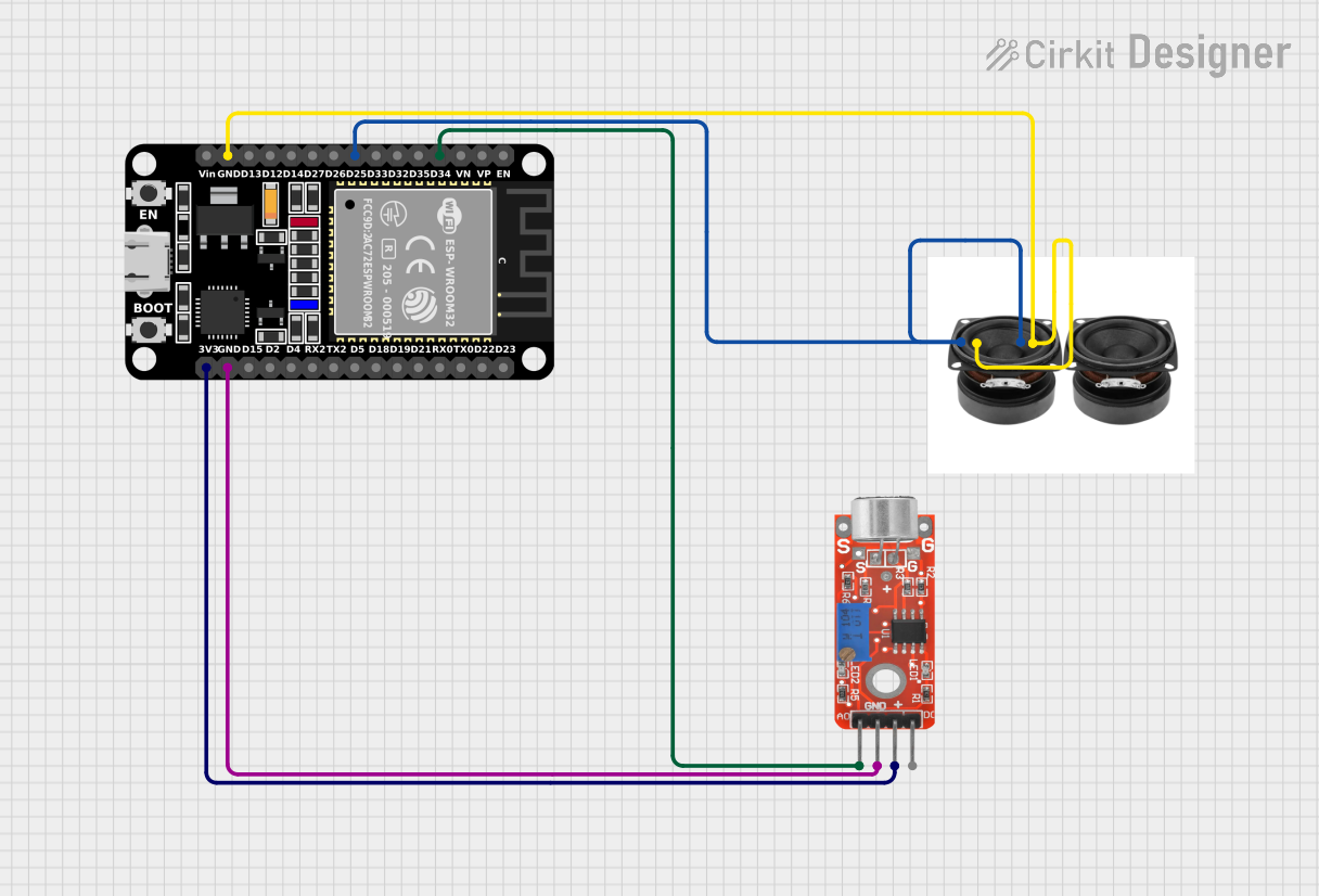
Circuit Documentation
Summary
This circuit is designed to interface an ESP32 microcontroller with a KY-037 microphone and a speaker. The ESP32 is programmed to connect to a Wi-Fi network and handle Over-the-Air (OTA) updates. The microphone captures audio input, which is then processed by the ESP32 and output through the speaker. This setup can be used for applications such as voice-controlled home automation with Google Assistant.
Component List
ESP32 (30 pin)
- Description: A powerful microcontroller with built-in Wi-Fi and Bluetooth capabilities.
- Pins: EN, VP, VN, D34, D35, D32, D33, D25, D26, D27, D14, D12, D13, GND, Vin, D23, D22, TX0, RX0, D21, D19, D18, D5, TX2, RX2, D4, D2, D15, 3V3
KY-037 Microphone
- Description: A microphone module that provides both analog and digital outputs.
- Pins: Analog output, Ground, VCC, Digital output
Speaker
- Description: A simple speaker for audio output.
- Pins: +, -
Wiring Details
ESP32 (30 pin)
- D34: Connected to KY-037 Microphone (Analog output)
- D25: Connected to Speaker (+)
- GND: Connected to Speaker (-) and KY-037 Microphone (Ground)
- 3V3: Connected to KY-037 Microphone (VCC)
KY-037 Microphone
- Analog output: Connected to ESP32 (D34)
- Ground: Connected to ESP32 (GND)
- VCC: Connected to ESP32 (3V3)
Speaker
- +: Connected to ESP32 (D25)
- -: Connected to ESP32 (GND)
Code Documentation
/*
 * Google Assistant for Home Automation
 * This code sets up the ESP32 to interface with Google Assistant
 * for controlling home automation devices. It includes a microphone
 * to listen and a speaker to reply.
 */

#include <WiFi.h>
#include <ESPmDNS.h>
#include <WiFiUdp.h>
#include <ArduinoOTA.h>

// Replace with your network credentials
const char* ssid = "your_SSID";
const char* password = "your_PASSWORD";

// Define pins for microphone and speaker
const int micPin = 34; // Example pin for microphone input
const int speakerPin = 25; // Example pin for speaker output

void setup() {
  // Initialize serial communication
  Serial.begin(115200);
  Serial.println("Booting");

  // Connect to Wi-Fi
  WiFi.begin(ssid, password);
  while (WiFi.status() != WL_CONNECTED) {
    delay(500);
    Serial.print(".");
  }
  Serial.println("");
  Serial.print("Connected to ");
  Serial.println(ssid);
  Serial.print("IP address: ");
  Serial.println(WiFi.localIP());

  // Start OTA (Over-the-Air) updates
  ArduinoOTA.begin();

  // Initialize microphone and speaker pins
  pinMode(micPin, INPUT);
  pinMode(speakerPin, OUTPUT);
}

void loop() {
  // Handle OTA updates
  ArduinoOTA.handle();

  // Main code to interface with Google Assistant
  // Add your code here to handle commands from Google Assistant

  // Example: Read from microphone and output to speaker
  int micValue = analogRead(micPin);
  analogWrite(speakerPin, micValue);
}
This code sets up the ESP32 to connect to a Wi-Fi network and handle OTA updates. It initializes the microphone and speaker pins and includes a simple loop to read audio input from the microphone and output it to the speaker. Additional code can be added to handle commands from Google Assistant for home automation purposes.