
Battery-Powered Light-Dependent LED Array with Transistor Control
View and Edit Project In Cirkit Designer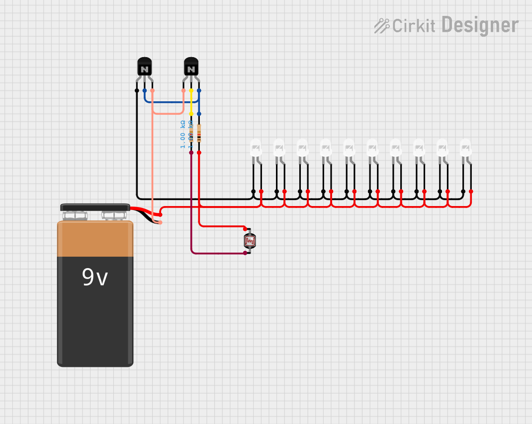
Circuit Documentation
Summary
This circuit is designed to control a series of white LEDs using a photocell (LDR) and NPN transistors. The circuit is powered by a 9V battery. The photocell detects the ambient light level and adjusts the brightness of the LEDs accordingly. The NPN transistors act as switches to control the current flow through the LEDs.
Component List
Photocell (LDR)
- Pins: pin 0, pin 1
- Description: Light-dependent resistor used to detect ambient light levels.
- Purpose: Adjusts the brightness of the LEDs based on the ambient light.
NPN Transistor (CBE)
- Pins: collector, base, emitter
- Description: NPN transistor used as a switch.
- Purpose: Controls the current flow through the LEDs.
NPN Transistor (CBE)
- Pins: collector, base, emitter
- Description: NPN transistor used as a switch.
- Purpose: Controls the current flow through the LEDs.
9V Battery
- Pins: -, +
- Description: Power source for the circuit.
- Purpose: Provides the necessary voltage to power the circuit.
LED: Two Pin (white)
- Pins: cathode, anode
- Description: White LED.
- Purpose: Emits light when current flows through it.
Resistor (1000 Ohms)
- Pins: pin1, pin2
- Description: Resistor with a resistance of 1000 Ohms.
- Purpose: Limits the current flow in the circuit.
Resistor (1000 Ohms)
- Pins: pin1, pin2
- Description: Resistor with a resistance of 1000 Ohms.
- Purpose: Limits the current flow in the circuit.
Wiring Details
Photocell (LDR)
pin 0 is connected to:
- Anode of multiple LEDs
- Pin 1 of a 1000 Ohm resistor
- Positive terminal of the 9V battery
pin 1 is connected to:
- Pin 1 of another 1000 Ohm resistor
NPN Transistor (CBE) 1
collector is connected to:
- Cathode of multiple LEDs
base is connected to:
- Pin 2 of a 1000 Ohm resistor
- Emitter of the second NPN transistor
emitter is connected to:
- Negative terminal of the 9V battery
- Collector of the second NPN transistor
NPN Transistor (CBE) 2
collector is connected to:
- Emitter of the first NPN transistor
base is connected to:
- Pin 2 of a 1000 Ohm resistor
emitter is connected to:
- Base of the first NPN transistor
9V Battery
+ is connected to:
- Anode of multiple LEDs
- Pin 1 of a 1000 Ohm resistor
- Pin 0 of the photocell
- is connected to:
- Emitter of the first NPN transistor
- Collector of the second NPN transistor
LED: Two Pin (white)
anode is connected to:
- Positive terminal of the 9V battery
- Pin 0 of the photocell
cathode is connected to:
- Collector of the first NPN transistor
Resistor (1000 Ohms) 1
pin1 is connected to:
- Pin 1 of the photocell
pin2 is connected to:
- Base of the second NPN transistor
Resistor (1000 Ohms) 2
pin1 is connected to:
- Pin 0 of the photocell
pin2 is connected to:
- Base of the first NPN transistor
- Emitter of the second NPN transistor
Code
There is no code associated with this circuit.