
Wi-Fi Controlled Smart Irrigation System with Soil Moisture Sensors and ESP8266
View and Edit Project In Cirkit Designer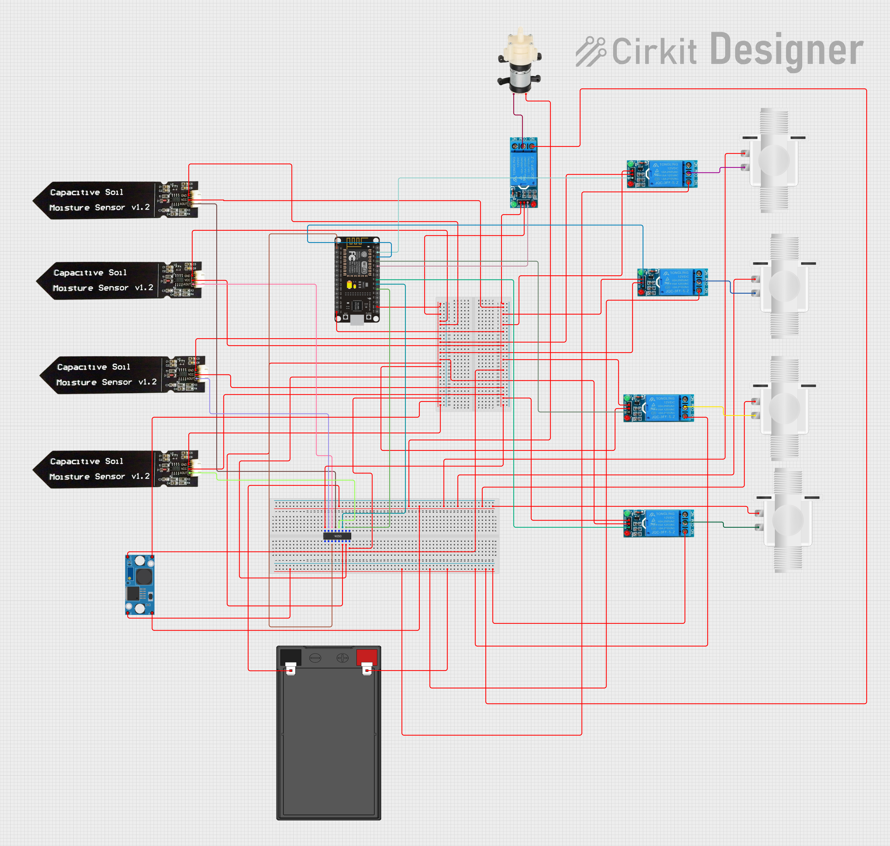
Circuit Documentation
Summary
This circuit is designed to monitor soil moisture levels using capacitive soil moisture sensors and control water flow through solenoid valves and a water pump. The system is managed by an ESP8266 NodeMCU microcontroller, which processes sensor data and actuates the relays to control the solenoid valves and water pump. The circuit is powered by a 12V 7Ah battery, with voltage regulation provided by an LM2596 step-down module.
Component List
Capacitive Soil Moisture Sensor V1.2
- Pins: GND, VCC, AOUT
- Description: Measures soil moisture levels.
- Purpose: Provides analog output proportional to soil moisture.
Plastic Solenoid Valve
- Pins: pin1, pin2
- Description: Controls water flow.
- Purpose: Opens or closes to allow or stop water flow.
Mini Diaphragm Water Pump
- Pins: Positive (+), Negative (-)
- Description: Pumps water.
- Purpose: Moves water through the system.
ESP8266 NodeMCU
- Pins: D0, D1, D2, D3, D4, 3V3, GND, D5, D6, D7, D8, RX, TX, A0, RSV, SD3, SD2, SD1, CMD, SD0, CLK, EN, RST, VIN
- Description: Microcontroller with Wi-Fi capabilities.
- Purpose: Processes sensor data and controls relays.
12V 7Ah Battery
- Pins: 12v +, 12v -
- Description: Provides power to the circuit.
- Purpose: Supplies 12V power.
12V Single Channel Relay
- Pins: NC, COM, NO, IN, GND, VCC
- Description: Electromechanical switch.
- Purpose: Controls high-power devices like solenoid valves and water pump.
4050 Hex Buffer
- Pins: VCC, NC, G, L, A, F, H, B, K, I, E, C, J, VSS, D
- Description: Logic level buffer.
- Purpose: Buffers and conditions signals.
LM2596 Step Down Module
- Pins: OUT-, OUT+, IN-, IN+
- Description: Voltage regulator.
- Purpose: Steps down voltage from 12V to 3.3V for the ESP8266.
Wiring Details
Capacitive Soil Moisture Sensor V1.2
- GND: Connected to GND net.
- VCC: Connected to VCC net.
- AOUT: Connected to:
- 4050 Hex Buffer pin L (for one sensor)
- 4050 Hex Buffer pin F (for another sensor)
- 4050 Hex Buffer pin NC (for another sensor)
- 4050 Hex Buffer pin K (for another sensor)
Plastic Solenoid Valve
- pin1: Connected to 12V 7Ah Battery 12v - net.
- pin2: Connected to:
- 12V Single Channel Relay COM pin (for one valve)
- 12V Single Channel Relay COM pin (for another valve)
- 12V Single Channel Relay COM pin (for another valve)
- 12V Single Channel Relay COM pin (for another valve)
Mini Diaphragm Water Pump
- Positive (+): Connected to 12V Single Channel Relay COM pin.
- Negative (-): Connected to 12V 7Ah Battery 12v - net.
ESP8266 NodeMCU
- VIN: Connected to VCC net.
- GND: Connected to GND net.
- A0: Connected to 4050 Hex Buffer pin A.
- D1: Connected to 12V Single Channel Relay IN pin.
- D2: Connected to 12V Single Channel Relay IN pin.
- D3: Connected to 12V Single Channel Relay IN pin.
- D4: Connected to 12V Single Channel Relay IN pin.
- D5: Connected to 12V Single Channel Relay IN pin.
- D6: Connected to 4050 Hex Buffer pin E.
- D7: Connected to 4050 Hex Buffer pin J.
12V 7Ah Battery
- 12v +: Connected to:
- LM2596 Step Down Module IN+ pin.
- 12V Single Channel Relay NO pin (for one relay)
- 12V Single Channel Relay NO pin (for another relay)
- 12V Single Channel Relay NO pin (for another relay)
- 12V Single Channel Relay NO pin (for another relay)
- 12v -: Connected to:
- Mini Diaphragm Water Pump Negative (-) pin.
- LM2596 Step Down Module IN- pin.
- Plastic Solenoid Valve pin1 (for one valve)
- Plastic Solenoid Valve pin1 (for another valve)
- Plastic Solenoid Valve pin1 (for another valve)
- Plastic Solenoid Valve pin1 (for another valve)
12V Single Channel Relay
- NC: Not connected.
- COM: Connected to:
- Plastic Solenoid Valve pin2 (for one relay)
- Plastic Solenoid Valve pin2 (for another relay)
- Plastic Solenoid Valve pin2 (for another relay)
- Plastic Solenoid Valve pin2 (for another relay)
- Mini Diaphragm Water Pump Positive (+) pin (for one relay)
- NO: Connected to 12V 7Ah Battery 12v + net.
- IN: Connected to:
- ESP8266 NodeMCU D1 pin (for one relay)
- ESP8266 NodeMCU D2 pin (for another relay)
- ESP8266 NodeMCU D3 pin (for another relay)
- ESP8266 NodeMCU D4 pin (for another relay)
- ESP8266 NodeMCU D5 pin (for another relay)
- GND: Connected to GND net.
- VCC: Connected to VCC net.
4050 Hex Buffer
- VCC: Connected to VCC net.
- NC: Connected to:
- Capacitive Soil Moisture Sensor V1.2 AOUT pin (for one sensor)
- 12V Single Channel Relay VCC pin (for one relay)
- 12V Single Channel Relay VCC pin (for another relay)
- 12V Single Channel Relay VCC pin (for another relay)
- ESP8266 NodeMCU VIN pin
- Capacitive Soil Moisture Sensor V1.2 VCC pin (for one sensor)
- 12V Single Channel Relay VCC pin (for another relay)
- LM2596 Step Down Module OUT+ pin
- Capacitive Soil Moisture Sensor V1.2 VCC pin (for another sensor)
- Capacitive Soil Moisture Sensor V1.2 VCC pin (for another sensor)
- 12V Single Channel Relay VCC pin (for another relay)
- G: Not connected.
- L: Connected to Capacitive Soil Moisture Sensor V1.2 AOUT pin.
- A: Connected to ESP8266 NodeMCU A0 pin.
- F: Connected to Capacitive Soil Moisture Sensor V1.2 AOUT pin.
- H: Not connected.
- B: Not connected.
- K: Connected to Capacitive Soil Moisture Sensor V1.2 AOUT pin.
- I: Connected to 4050 Hex Buffer pin C.
- E: Connected to ESP8266 NodeMCU D6 pin.
- C: Connected to 4050 Hex Buffer pin I.
- J: Connected to ESP8266 NodeMCU D7 pin.
- VSS: Connected to GND net.
- D: Not connected.
LM2596 Step Down Module
- OUT-: Connected to GND net.
- OUT+: Connected to VCC net.
- IN-: Connected to 12V 7Ah Battery 12v - net.
- IN+: Connected to 12V 7Ah Battery 12v + net.
Code
No code provided for this circuit.
This documentation provides a comprehensive overview of the circuit, including a summary, component list, wiring details, and code section. Each component is described, and its connections are detailed to ensure clarity and ease of understanding.