
Arduino UNO Controlled Servo Motor with HX711 Load Cell Feedback
View and Edit Project In Cirkit Designer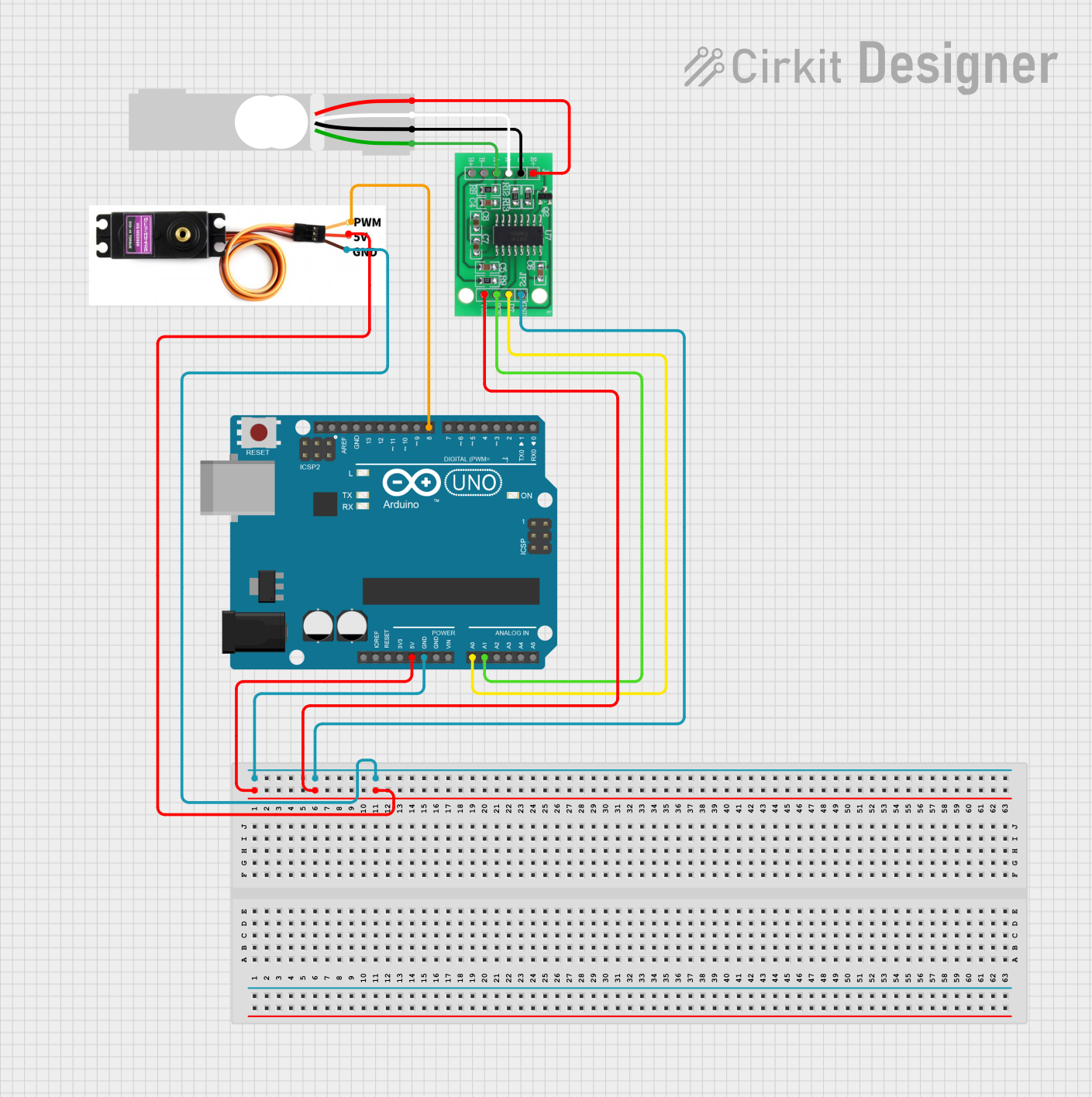
Circuit Documentation
Summary of the Circuit
This circuit integrates an Arduino UNO microcontroller with an HX711 bridge sensor interface and a load cell to measure weight or force. Additionally, a Servo Motor MG996R is included for actuation purposes. The Arduino UNO is responsible for controlling the servo motor and reading data from the HX711, which in turn reads from the load cell. The HX711 is powered by the 5V supply from the Arduino and communicates with the Arduino via two digital pins. The servo motor is also powered by the 5V supply and receives pulse width modulation (PWM) control signals from the Arduino.
Component List
Arduino UNO
- Microcontroller board based on the ATmega328P
- It has 14 digital input/output pins, 6 analog inputs, a 16 MHz quartz crystal, a USB connection, a power jack, an ICSP header, and a reset button.
HX711 - Bridge Sensor Interface
- A precision 24-bit analog-to-digital converter (ADC) designed for weigh scales and industrial control applications to interface directly with a bridge sensor.
Load Cell - Red/white/black/green
- A transducer that converts force into an electrical signal. This load cell is typically used in weighing systems and has four wires corresponding to the excitation and signal outputs.
Servo Motor MG996R
- A high-torque servo motor capable of precise position control. It is commonly used in robotics, RC vehicles, and other control systems.
Wiring Details
Arduino UNO
- 5V supplies power to the HX711 and the Servo Motor MG996R.
- GND is connected to the ground pins of the HX711 and the Servo Motor MG996R to complete the power circuit.
- A0 is connected to the DATA (OUT) pin of the HX711 for data communication.
- A1 is connected to the SCK - CLOCK (IN) pin of the HX711 to provide the clock signal.
- D8 is connected to the PWM input of the Servo Motor MG996R for control signals.
HX711 - Bridge Sensor Interface
- 3.3/3.5V Supply receives power from the Arduino UNO's 5V pin.
- GND - GROUND is connected to the Arduino UNO's GND.
- DATA (OUT) sends data to the Arduino UNO's A0 pin.
- SCK - CLOCK (IN) receives the clock signal from the Arduino UNO's A1 pin.
- E+, E-, A+, A- are connected to the corresponding pins of the Load Cell.
Load Cell - Red/white/black/green
- E+ and E- are connected to the excitation voltage supply and ground of the HX711.
- A+ and A- are connected to the signal output pins of the HX711.
Servo Motor MG996R
- VCC 5V receives power from the Arduino UNO's 5V pin.
- GND is connected to the Arduino UNO's GND.
- PMW receives PWM control signals from the Arduino UNO's D8 pin.
Documented Code
Arduino UNO Code (sketch.ino)
void setup() {
  // put your setup code here, to run once:

}

void loop() {
  // put your main code here, to run repeatedly:

}
Note: The provided code is a template and does not include specific functionality. It should be populated with the necessary setup and loop code to initialize the HX711 and Servo Motor MG996R and to handle data communication and motor control.