
Function Generator and Oscilloscope-Based RLC Circuit Analysis
View and Edit Project In Cirkit Designer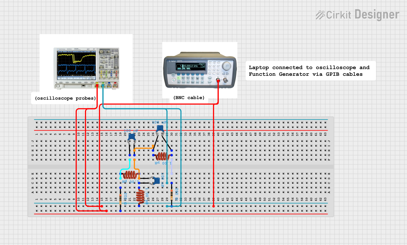
Circuit Documentation
Summary
This document provides a detailed overview of a circuit design, including a list of components, their descriptions, wiring details, and any embedded code. The circuit includes various passive components such as resistors, inductors, and capacitors, as well as a function generator and a mixed signal oscilloscope.
Component List
Function Generator
- Pins: sync, Output
- Description: Generates various types of electrical waveforms over a wide range of frequencies.
- Purpose: Used to provide input signals to the circuit.
Resistor
- Pins: pin1, pin2
- Description: A passive electrical component that implements electrical resistance as a circuit element.
- Purpose: Used to limit current flow and divide voltages.
- Properties:
- Resistance: 200 Ohms
Mixed Signal Oscilloscope
- Pins: 1, 2, 3, 4
- Description: An oscilloscope that can measure both analog and digital signals.
- Purpose: Used to observe the varying signal voltages in the circuit.
Inductor
- Pins: pin 0, pin 1
- Description: A passive electrical component that stores energy in a magnetic field when electric current flows through it.
- Purpose: Used to filter signals, store energy, and create magnetic fields.
- Properties:
- Inductance: 0.000001 Henrys
Ceramic Capacitor
- Pins: pin0, pin1
- Description: A capacitor that uses a ceramic material as the dielectric.
- Purpose: Used to store electrical energy temporarily, filter signals, and block DC while allowing AC to pass.
- Properties:
- Capacitance: 0.0000001 Farads
Wiring Details
Function Generator
- sync pin is connected to:
- Mixed Signal Oscilloscope pin 2
- Mixed Signal Oscilloscope pin 1
Resistor
pin1 is connected to:
- Inductor pin 1
- Ceramic Capacitor pin0
pin2 is connected to:
- Mixed Signal Oscilloscope pin 2
- Mixed Signal Oscilloscope pin 1
Mixed Signal Oscilloscope
pin 1 is connected to:
- Function Generator sync pin
- Resistor pin2
pin 2 is connected to:
- Function Generator sync pin
- Resistor pin2
Inductor
pin 0 is connected to:
- Inductor pin 0
- Ceramic Capacitor pin0
- Ceramic Capacitor pin1
- Inductor pin 1
- Ceramic Capacitor pin0
pin 1 is connected to:
- Resistor pin1
- Ceramic Capacitor pin0
Ceramic Capacitor
pin0 is connected to:
- Inductor pin 0
- Inductor pin 1
- Ceramic Capacitor pin1
pin1 is connected to:
- Inductor pin 0
- Ceramic Capacitor pin0
Embedded Code
No embedded code is present in this circuit design.
This document provides a comprehensive overview of the circuit, detailing each component and its connections. This should serve as a useful reference for understanding and troubleshooting the circuit.