Cirkit Designer
Your all-in-one circuit design IDE
Home /
Project Documentation
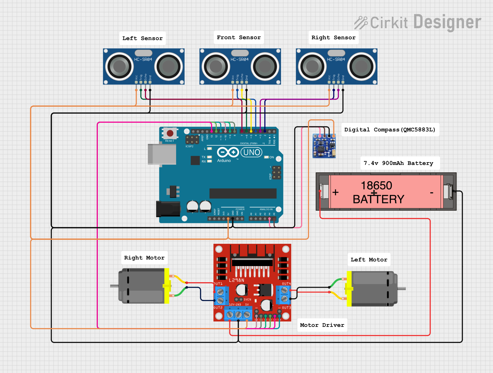
Arduino UNO-Based Battery-Powered Robotic System with Ultrasonic Sensors and Magnetometer
Circuit Documentation
Summary
This circuit involves an Arduino UNO microcontroller interfacing with multiple sensors and a motor driver to control two DC motors. The sensors include a QMC5883L magnetometer and three HC-SR04 ultrasonic sensors. The circuit is powered by a Li-ion 18650 battery. The L298N motor driver is used to control the DC motors.
Component List
Arduino UNO
- Description: A microcontroller board based on the ATmega328P.
- Pins: UNUSED, IOREF, Reset, 3.3V, 5V, GND, Vin, A0, A1, A2, A3, A4, A5, SCL, SDA, AREF, D13, D12, D11, D10, D9, D8, D7, D6, D5, D4, D3, D2, D1, D0
QMC5883L Magnetometer
- Description: A 3-axis digital compass.
- Pins: VCC, GND, SCL, SDA, DRDY
HC-SR04 Ultrasonic Sensor
- Description: A sensor used for distance measurement.
- Pins: VCC, TRIG, ECHO, GND
Li-ion 18650 Battery
- Description: A rechargeable lithium-ion battery.
- Pins: -, +
L298N DC Motor Driver
- Description: A dual H-Bridge motor driver.
- Pins: OUT1, OUT2, 12V, GND, 5V, OUT3, OUT4, 5V-ENA-JMP-I, 5V-ENA-JMP-O, +5V-J1, +5V-J2, ENA, IN1, IN2, IN3, IN4, ENB
DC Motor
- Description: A simple DC motor.
- Pins: pin 1, pin 2
Wiring Details
Arduino UNO
- 5V: Connected to VCC of QMC5883L Magnetometer, VCC of all HC-SR04 Ultrasonic Sensors, and 5V of L298N DC Motor Driver.
- GND: Connected to GND of QMC5883L Magnetometer, GND of all HC-SR04 Ultrasonic Sensors, GND of L298N DC Motor Driver, and - of Li-ion 18650 Battery.
- A4: Connected to SDA of QMC5883L Magnetometer.
- A5: Connected to SCL of QMC5883L Magnetometer.
- D13: Connected to IN4 of L298N DC Motor Driver.
- D12: Connected to IN3 of L298N DC Motor Driver.
- D11: Connected to ENB of L298N DC Motor Driver.
- D10: Connected to ENA of L298N DC Motor Driver.
- D9: Connected to IN2 of L298N DC Motor Driver.
- D8: Connected to IN1 of L298N DC Motor Driver.
- D7: Connected to ECHO of one HC-SR04 Ultrasonic Sensor.
- D6: Connected to TRIG of one HC-SR04 Ultrasonic Sensor.
- D5: Connected to ECHO of another HC-SR04 Ultrasonic Sensor.
- D4: Connected to TRIG of another HC-SR04 Ultrasonic Sensor.
- D3: Connected to ECHO of the third HC-SR04 Ultrasonic Sensor.
- D2: Connected to TRIG of the third HC-SR04 Ultrasonic Sensor.
QMC5883L Magnetometer
- VCC: Connected to 5V of Arduino UNO.
- GND: Connected to GND of Arduino UNO.
- SDA: Connected to A4 of Arduino UNO.
- SCL: Connected to A5 of Arduino UNO.
HC-SR04 Ultrasonic Sensor (1)
- VCC: Connected to 5V of Arduino UNO.
- GND: Connected to GND of Arduino UNO.
- TRIG: Connected to D2 of Arduino UNO.
- ECHO: Connected to D3 of Arduino UNO.
HC-SR04 Ultrasonic Sensor (2)
- VCC: Connected to 5V of Arduino UNO.
- GND: Connected to GND of Arduino UNO.
- TRIG: Connected to D4 of Arduino UNO.
- ECHO: Connected to D5 of Arduino UNO.
HC-SR04 Ultrasonic Sensor (3)
- VCC: Connected to 5V of Arduino UNO.
- GND: Connected to GND of Arduino UNO.
- TRIG: Connected to D6 of Arduino UNO.
- ECHO: Connected to D7 of Arduino UNO.
Li-ion 18650 Battery
- -: Connected to GND of Arduino UNO.
- +: Connected to 12V of L298N DC Motor Driver.
L298N DC Motor Driver
- 5V: Connected to 5V of Arduino UNO.
- GND: Connected to GND of Arduino UNO.
- IN1: Connected to D8 of Arduino UNO.
- IN2: Connected to D9 of Arduino UNO.
- IN3: Connected to D12 of Arduino UNO.
- IN4: Connected to D13 of Arduino UNO.
- ENA: Connected to D10 of Arduino UNO.
- ENB: Connected to D11 of Arduino UNO.
- OUT1: Connected to pin 2 of one DC Motor.
- OUT2: Connected to pin 1 of one DC Motor.
- OUT3: Connected to pin 1 of another DC Motor.
- OUT4: Connected to pin 2 of another DC Motor.
DC Motor (1)
- pin 1: Connected to OUT2 of L298N DC Motor Driver.
- pin 2: Connected to OUT1 of L298N DC Motor Driver.
DC Motor (2)
- pin 1: Connected to OUT3 of L298N DC Motor Driver.
- pin 2: Connected to OUT4 of L298N DC Motor Driver.
Code Documentation
Arduino UNO Code
void setup() {
  // put your setup code here, to run once:

}

void loop() {
  // put your main code here, to run repeatedly:

}
This code is a basic template for the Arduino UNO. The setup() function is where you initialize your components and set up your initial conditions. The loop() function is where you place the code that you want to run continuously.