Cellular-Connected ESP32-CAM with Real-Time Clock and Isolated Control

Circuit Documentation
Summary
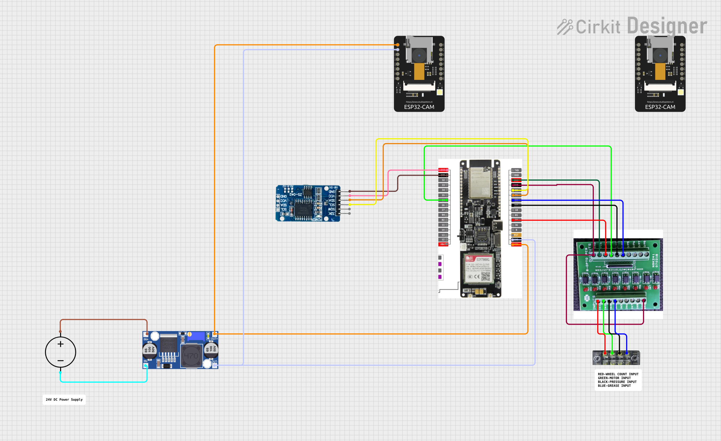
The circuit in question appears to be a complex system involving communication and control elements. It includes a microcontroller unit (ESP32-CAM), a GSM/GPRS/GPS module (LilyGo-SIM7000G), a Real-Time Clock (RTC DS3231), an 8-channel opto-coupler for isolation, a buck converter for voltage regulation, and a DC power source. The circuit is designed to interface with external signals through a terminal block and to manage power distribution and signal isolation effectively.
Component List
8-Channel OPTO-COUPLER
- Description: An opto-coupler with 8 channels used for electrical signal isolation.
- Pins: COM GND, IN8-IN1, GND, VCC, OP1-OP8
Terminal Block (04-01)
- Description: A terminal block used for connecting external wires to the circuit.
- Pins: 1-8
ESP32 - CAM
- Description: A microcontroller unit with camera capabilities.
- Pins: 5V, GND, IO12-IO16, IO2, IO4, VOT, VOR, VCC, 3V3
Buck Converter
- Description: A DC-DC converter that steps down voltage.
- Pins: IN+, IN-, OUT+, OUT-
DC Power Source
- Description: A source of DC power for the circuit.
- Pins: Ground, Positive
RTC DS3231
- Description: A real-time clock module for timekeeping.
- Pins: 32K, SQW, SCL, SDA, VCC, GND
LilyGo-SIM7000G
- Description: A module with GSM/GPRS/GPS capabilities.
- Pins: 3V3, GND, 32-35, 25-27, 04, 02, 15-19, 23, 21, 22, RXD, TXD, VBAT, VIN, RST, 0, 36, 39, 05, 18
Wiring Details
8-Channel OPTO-COUPLER
- COM GND connected to LilyGo-SIM7000G GND
- IN1-IN4 connected to Terminal Block pins 1, 3, 5, 7 respectively
- GND connected to LilyGo-SIM7000G GND
- VCC connected to LilyGo-SIM7000G 3V3
- OP1-OP4 connected to LilyGo-SIM7000G pins 39, 25, 19, 23 respectively
Terminal Block (04-01)
- Pins 1, 3, 5, 7 connected to 8-Channel OPTO-COUPLER IN1-IN4 respectively
ESP32 - CAM
- 5V connected to Buck Converter OUT+
- GND connected to Buck Converter OUT-
Buck Converter
- IN+ connected to DC Power Source Positive
- IN- connected to DC Power Source Ground
- OUT+ connected to ESP32 - CAM 5V
- OUT- connected to ESP32 - CAM GND
DC Power Source
- Positive connected to Buck Converter IN+
- Ground connected to Buck Converter IN-
RTC DS3231
- SCL connected to LilyGo-SIM7000G pin 22
- SDA connected to LilyGo-SIM7000G pin 21
- VCC connected to LilyGo-SIM7000G 3V3
- GND connected to LilyGo-SIM7000G GND
LilyGo-SIM7000G
- 3V3 connected to RTC DS3231 VCC and 8-Channel OPTO-COUPLER VCC
- GND connected to RTC DS3231 GND, 8-Channel OPTO-COUPLER COM GND and GND
- 22 (SCL) connected to RTC DS3231 SCL
- 21 (SDA) connected to RTC DS3231 SDA
- 25, 39, 19, 23 connected to 8-Channel OPTO-COUPLER OP2, OP1, OP3, OP4 respectively
- VIN connected to ESP32 - CAM 5V
Documented Code
No code was provided for the microcontrollers in the circuit. If code is available, it should be documented here with explanations for each function and routine, including setup and loop functions, interrupt service routines, and any communication protocol implementations.