
Arduino and ESP8266-Based Smart Home Automation System with RGB LED and Sensor Integration
View and Edit Project In Cirkit Designer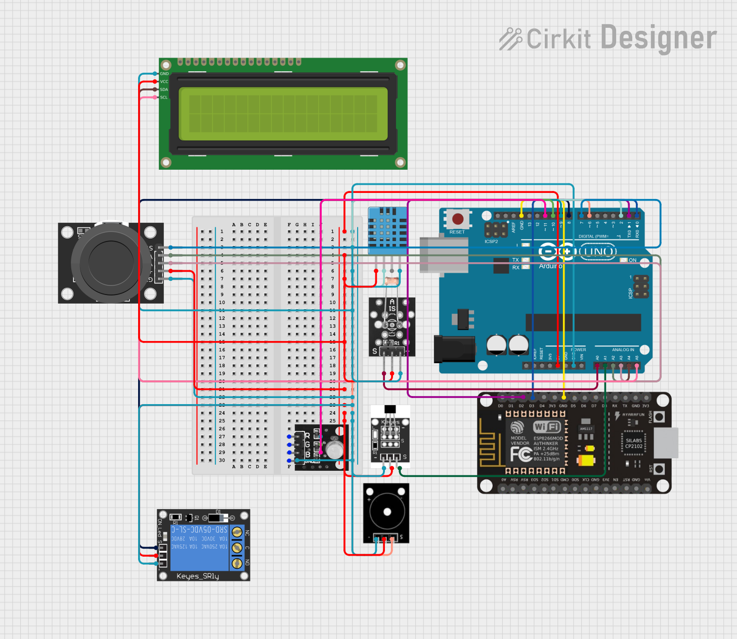
Circuit Documentation
Summary
This circuit involves an Arduino UNO microcontroller interfacing with various sensors, actuators, and modules. The components include an ESP8266 NodeMCU, resistors, an RGB LED module, a photoresistor, a DHT11 humidity and temperature sensor, a joystick module, a relay, a passive buzzer, a Hall sensor, and a 16x2 I2C LCD. The Arduino UNO serves as the central controller, reading sensor data and controlling the actuators.
Component List
Arduino UNO
- Description: A microcontroller board based on the ATmega328P.
- Pins: UNUSED, IOREF, Reset, 3.3V, 5V, GND, Vin, A0, A1, A2, A3, A4, A5, SCL, SDA, AREF, D13, D12, D11, D10, D9, D8, D7, D6, D5, D4, D3, D2, D1, D0
ESP8266 NodeMCU
- Description: A low-cost Wi-Fi microchip with full TCP/IP stack and microcontroller capability.
- Pins: D0, D1, D2, D3, D4, 3V3, GND, D5, D6, D7, D8, RX, TX, A0, RSV, SD3, SD2, SD1, CMD, SD0, CLK, EN, RST, VIN
Resistor
- Description: A passive electrical component that implements electrical resistance.
- Pins: pin1, pin2
- Properties: Resistance: 200 Ohms
Hall Sensor
- Description: A sensor that detects the presence of a magnetic field.
- Pins: -, +, S
KY-023 Dual Axis Joystick Module
- Description: A joystick module that provides analog output for X and Y axes and a digital output for the switch.
- Pins: GND, +5V, VRx, VRy, SW
1-Channel Relay (5V 10A)
- Description: A relay module that allows control of high voltage devices.
- Pins: NC, signal, C, power, NO, ground
DHT11 Humidity and Temperature Sensor
- Description: A sensor that measures temperature and humidity.
- Pins: VDD, DATA, NULL, GND
Elegoo Passive Buzzer
- Description: A buzzer that produces sound when a voltage is applied.
- Pins: GND, VCC, OUTPUT
RGB LED Module
- Description: An LED module with red, green, and blue LEDs.
- Pins: +VCC Red, +VCC Green, +VCC Blue, GND
KY-018 LDR Photo Resistor
- Description: A light-dependent resistor that changes resistance based on light intensity.
- Pins: Signal, VCC, Ground
16x2 I2C LCD
- Description: A 16x2 character LCD with I2C interface.
- Pins: GND, VCC, SDA, SCL
Wiring Details
Arduino UNO
- D9: Connected to +VCC Red of RGB LED module through a 200 Ohm resistor
- D10: Connected to +VCC Green of RGB LED module through a 200 Ohm resistor
- D11: Connected to +VCC Blue of RGB LED module through a 200 Ohm resistor
- GND: Connected to GND of RGB LED module, KY-018 LDR Photo Resistor, DHT11 Humidity and Temperature Sensor, 16x2 I2C LCD, KY-023 Dual Axis Joystick Module, 1-Channel Relay, Elegoo Passive Buzzer, Hall Sensor, and ESP8266 NodeMCU
- 5V: Connected to VCC of KY-018 LDR Photo Resistor, DHT11 Humidity and Temperature Sensor, 16x2 I2C LCD, +5V of KY-023 Dual Axis Joystick Module, power of 1-Channel Relay, VCC of Elegoo Passive Buzzer, and + of Hall Sensor
- A0: Connected to Signal of KY-018 LDR Photo Resistor
- A1: Connected to S of Hall Sensor
- A2: Connected to VRy of KY-023 Dual Axis Joystick Module
- A3: Connected to VRx of KY-023 Dual Axis Joystick Module
- A4: Connected to SDA of 16x2 I2C LCD
- A5: Connected to SCL of 16x2 I2C LCD
- D8: Connected to signal of 1-Channel Relay
- D7: Connected to SW of KY-023 Dual Axis Joystick Module
- D6: Connected to OUTPUT of Elegoo Passive Buzzer
- D2: Connected to DATA of DHT11 Humidity and Temperature Sensor
- D1: Connected to D2 of ESP8266 NodeMCU
- D0: Connected to D3 of ESP8266 NodeMCU
ESP8266 NodeMCU
- GND: Connected to GND of Arduino UNO
- D2: Connected to D1 of Arduino UNO
- D3: Connected to D0 of Arduino UNO
Resistor
- pin1: Connected to pin2 of the same resistor and +VCC Red of RGB LED module, then to D9 of Arduino UNO
- pin1: Connected to pin2 of the same resistor and +VCC Green of RGB LED module, then to D10 of Arduino UNO
- pin1: Connected to pin2 of the same resistor and +VCC Blue of RGB LED module, then to D11 of Arduino UNO
RGB LED Module
- +VCC Red: Connected to D9 of Arduino UNO through a 200 Ohm resistor
- +VCC Green: Connected to D10 of Arduino UNO through a 200 Ohm resistor
- +VCC Blue: Connected to D11 of Arduino UNO through a 200 Ohm resistor
- GND: Connected to GND of Arduino UNO
KY-018 LDR Photo Resistor
- Signal: Connected to A0 of Arduino UNO
- VCC: Connected to 5V of Arduino UNO
- Ground: Connected to GND of Arduino UNO
DHT11 Humidity and Temperature Sensor
- VDD: Connected to 5V of Arduino UNO
- DATA: Connected to D2 of Arduino UNO
- GND: Connected to GND of Arduino UNO
KY-023 Dual Axis Joystick Module
- GND: Connected to GND of Arduino UNO
- +5V: Connected to 5V of Arduino UNO
- VRx: Connected to A3 of Arduino UNO
- VRy: Connected to A2 of Arduino UNO
- SW: Connected to D7 of Arduino UNO
1-Channel Relay (5V 10A)
- NC: Not connected
- signal: Connected to D8 of Arduino UNO
- C: Not connected
- power: Connected to 5V of Arduino UNO
- NO: Not connected
- ground: Connected to GND of Arduino UNO
Elegoo Passive Buzzer
- GND: Connected to GND of Arduino UNO
- VCC: Connected to 5V of Arduino UNO
- OUTPUT: Connected to D6 of Arduino UNO
Hall Sensor
- -: Connected to GND of Arduino UNO
- +: Connected to 5V of Arduino UNO
- S: Connected to A1 of Arduino UNO
16x2 I2C LCD
- GND: Connected to GND of Arduino UNO
- VCC: Connected to 5V of Arduino UNO
- SDA: Connected to A4 of Arduino UNO
- SCL: Connected to A5 of Arduino UNO
Documented Code
Arduino UNO Code
void setup() {
  // put your setup code here, to run once:

}

void loop() {
  // put your main code here, to run repeatedly:

}
This code is a basic template for the Arduino UNO. The setup() function is where you initialize your components and settings, and the loop() function is where you place the main logic that runs repeatedly.