
Circuit Documentation
Summary of the Circuit
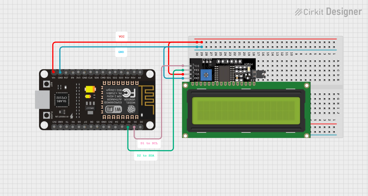
This circuit consists of an ESP8266 NodeMCU microcontroller unit (MCU) connected to an LCD Display (16x4 characters) with an I2C interface. The ESP8266 NodeMCU provides the processing power and GPIO pins necessary for interfacing with the LCD Display. The display is used to show data or messages, which are controlled by the ESP8266 NodeMCU. The I2C communication protocol is used to minimize the number of pins required for the interface, allowing for a simpler and more efficient design.
Component List
ESP8266 NodeMCU
- Description: A Wi-Fi enabled microcontroller with a variety of digital I/O pins.
- Pins: D0, D1, D2, D3, D4, 3V3, GND, D5, D6, D7, D8, RX, TX, A0, RSV, SD3, SD2, SD1, CMD, SD0, CLK, EN, RST, VIN
LCD Display 16x4 I2C
- Description: A 16x4 character LCD display with an I2C communication interface.
- Pins: SCL, SDA, VCC, GND
Wiring Details
ESP8266 NodeMCU
- VIN: Connected to the VCC of the LCD Display to provide power.
- GND: Connected to the GND of the LCD Display to complete the power circuit.
- D1: Configured as SCL (Serial Clock Line) for I2C communication with the LCD Display.
- D2: Configured as SDA (Serial Data Line) for I2C communication with the LCD Display.
LCD Display 16x4 I2C
- VCC: Connected to the VIN of the ESP8266 NodeMCU to receive power.
- GND: Connected to the GND of the ESP8266 NodeMCU to complete the power circuit.
- SCL: Connected to the D1 pin of the ESP8266 NodeMCU for I2C communication.
- SDA: Connected to the D2 pin of the ESP8266 NodeMCU for I2C communication.
Documented Code
There is no code provided for the microcontroller in this circuit. The code would typically initialize the I2C interface on the ESP8266 NodeMCU and contain functions to send data to the LCD Display for output. Without the code, the functionality of the circuit cannot be fully described. However, the expected code would set up the I2C communication, clear the display, set the cursor position, and write messages to the display.