
Circuit Documentation
Summary
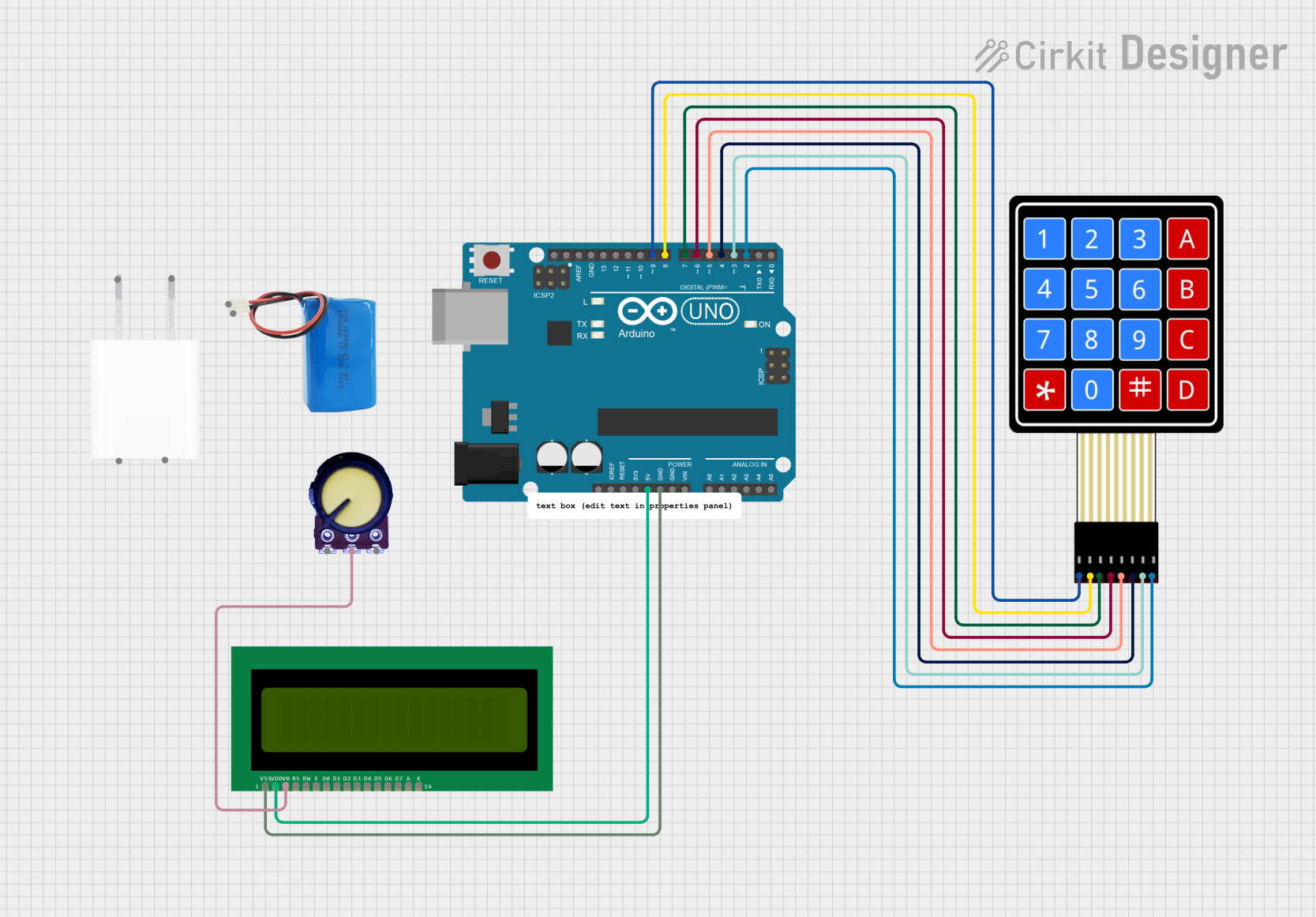
This project is an IC Tester that uses an Arduino UNO to interface with a 4x4 Membrane Matrix Keypad and a 16x2 LCD. The user inputs the IC pin configuration via the keypad, and the Arduino checks the IC functionality and displays the result on the LCD. A potentiometer is used to adjust the contrast of the LCD.
Component List
Arduino UNO
- Description: A microcontroller board based on the ATmega328P.
- Pins: UNUSED, IOREF, Reset, 3.3V, 5V, GND, Vin, A0, A1, A2, A3, A4, A5, SCL, SDA, AREF, D13, D12, D11, D10, D9, D8, D7, D6, D5, D4, D3, D2, D1, D0
4x4 Membrane Matrix Keypad
- Description: A keypad with 4 rows and 4 columns.
- Pins: R1, R2, R3, R4, C1, C2, C3, C4
16x2 LCD
- Description: A liquid crystal display with 16 columns and 2 rows.
- Pins: VSS, VDD, V0, RS, RW, E, D1, D0, D2, D3, D4, D6, D5, D7, A, K
Potentiometer
- Description: A variable resistor used to adjust the contrast of the LCD.
- Pins: GND, Output, VCC
5V Adapter
- Description: A power adapter providing 5V output.
- Pins: AC In 1, AC In 2, 5V, GND
5V Battery
- Description: A battery providing 5V output.
- Pins: positive, negative
Wiring Details
Arduino UNO
- 5V connected to VDD of 16x2 LCD
- GND connected to VSS of 16x2 LCD
- D9 connected to R1 of 4x4 Membrane Matrix Keypad
- D8 connected to R2 of 4x4 Membrane Matrix Keypad
- D7 connected to R3 of 4x4 Membrane Matrix Keypad
- D6 connected to R4 of 4x4 Membrane Matrix Keypad
- D5 connected to C1 of 4x4 Membrane Matrix Keypad
- D4 connected to C2 of 4x4 Membrane Matrix Keypad
- D3 connected to C3 of 4x4 Membrane Matrix Keypad
- D2 connected to C4 of 4x4 Membrane Matrix Keypad
4x4 Membrane Matrix Keypad
- R1 connected to D9 of Arduino UNO
- R2 connected to D8 of Arduino UNO
- R3 connected to D7 of Arduino UNO
- R4 connected to D6 of Arduino UNO
- C1 connected to D5 of Arduino UNO
- C2 connected to D4 of Arduino UNO
- C3 connected to D3 of Arduino UNO
- C4 connected to D2 of Arduino UNO
16x2 LCD
- VDD connected to 5V of Arduino UNO
- VSS connected to GND of Arduino UNO
- V0 connected to Output of Potentiometer
Potentiometer
- Output connected to V0 of 16x2 LCD
Code Documentation
/*
 * Project: IC Tester
 * Description: This code tests an SN7400N IC using a keypad and displays the
 * result on a 16x2 LCD. The user inputs the IC pin configuration via the keypad,
 * and the Arduino checks the IC functionality.
 */

#include <Keypad.h>
#include <LiquidCrystal.h>

// Keypad configuration
const byte ROWS = 4; // Four rows
const byte COLS = 4; // Four columns
char keys[ROWS][COLS] = {
  {'1','2','3','A'},
  {'4','5','6','B'},
  {'7','8','9','C'},
  {'*','0','#','D'}
};
byte rowPins[ROWS] = {9, 8, 7, 6}; // Connect to the row pinouts of the keypad
byte colPins[COLS] = {5, 4, 3, 2}; // Connect to the column pinouts of the keypad
Keypad keypad = Keypad(makeKeymap(keys), rowPins, colPins, ROWS, COLS);

// LCD configuration
LiquidCrystal lcd(12, 11, 5, 4, 3, 2);

void setup() {
  // Initialize the LCD
  lcd.begin(16, 2);
  lcd.print("IC Tester");
  delay(2000);
  lcd.clear();
  lcd.print("Enter IC config");
}

void loop() {
  char key = keypad.getKey();
  if (key) {
    lcd.clear();
    lcd.print("Key Pressed: ");
    lcd.print(key);
    // Add logic to test IC based on key input
  }
}
This code initializes the keypad and LCD, and waits for user input from the keypad. When a key is pressed, it displays the key on the LCD. Additional logic can be added to test the IC based on the key input.