
Wi-Fi Enabled Smart Lid Status Monitor with NodeMCU and RGB LED
View and Edit Project In Cirkit Designer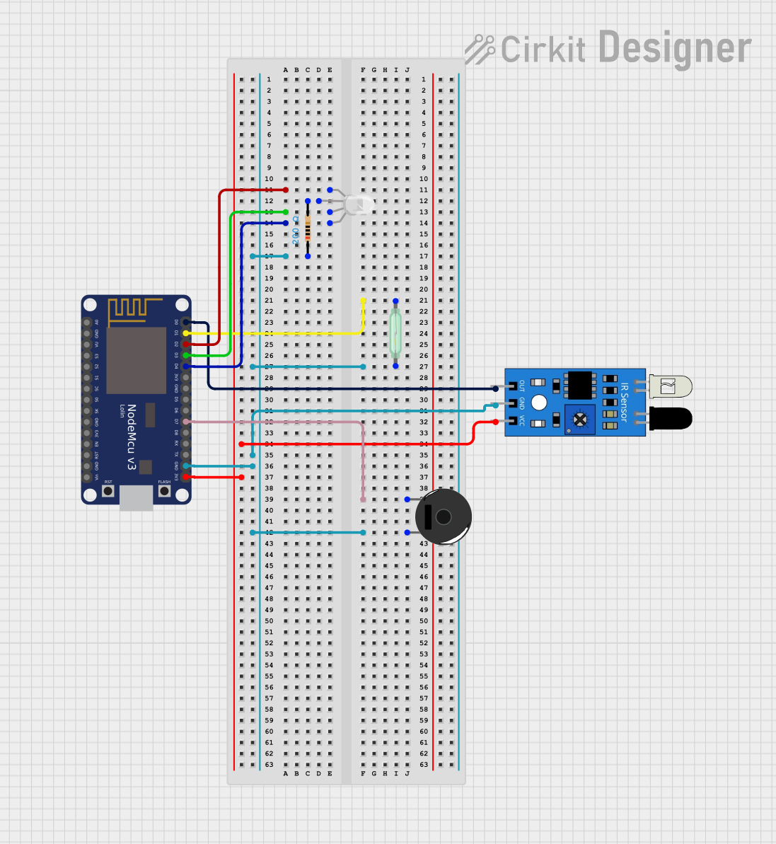
Circuit Documentation
Summary
This circuit involves a NodeMCU V3 ESP8266 microcontroller interfacing with an RGB LED, an IR sensor, a Reed Switch, a Piezo Buzzer, and a Resistor. The NodeMCU reads the state of the Reed Switch and controls the RGB LED and Piezo Buzzer based on the input from the IR sensor.
Component List
NodeMCU V3 ESP8266
- Description: A microcontroller with built-in Wi-Fi capabilities.
- Pins: A0, GND, VU, S3, S2, S1, SC, S0, SK, 3V3, EN, RST, Vin, D0, D1, D2, D3, D4, D5, D6, D7, D8, RX, TX
IR Sensor
- Description: An infrared sensor used for detecting objects.
- Pins: out, gnd, vcc
Reed Switch
- Description: A magnetic switch that opens or closes in the presence of a magnetic field.
- Pins: pin 1, pin 2
RGB LED (Wokwi compatible)
- Description: A light-emitting diode with red, green, and blue channels.
- Pins: R, COM, G, B
Resistor
- Description: A 200 Ohms resistor used to limit current.
- Pins: pin1, pin2
- Properties:
- Resistance: 200 Ohms
Piezo Buzzer
- Description: A buzzer that produces sound when a voltage is applied.
- Pins: pin 1, pin 2
Wiring Details
NodeMCU V3 ESP8266
- D0: Connected to IR Sensor (out)
- D1: Connected to Reed Switch (pin 2)
- D2: Connected to RGB LED (R)
- D3: Connected to RGB LED (G)
- D4: Connected to RGB LED (B)
- D7: Connected to Piezo Buzzer (pin 1)
- GND: Connected to IR Sensor (gnd), Resistor (pin1), Reed Switch (pin 1), Piezo Buzzer (pin 2)
- 3V3: Connected to IR Sensor (vcc)
IR Sensor
- out: Connected to NodeMCU (D0)
- gnd: Connected to NodeMCU (GND)
- vcc: Connected to NodeMCU (3V3)
Reed Switch
- pin 1: Connected to Resistor (pin1), NodeMCU (GND)
- pin 2: Connected to NodeMCU (D1)
RGB LED (Wokwi compatible)
- R: Connected to NodeMCU (D2)
- G: Connected to NodeMCU (D3)
- B: Connected to NodeMCU (D4)
- COM: Connected to Resistor (pin2)
Resistor
- pin1: Connected to Reed Switch (pin 1), NodeMCU (GND)
- pin2: Connected to RGB LED (COM)
Piezo Buzzer
- pin 1: Connected to NodeMCU (D7)
- pin 2: Connected to NodeMCU (GND)
Code Documentation
NodeMCU V3 ESP8266 Code
void setup() {
  pinMode(D1, INPUT_PULLUP); // Enable internal pull-up resistor on D1
  Serial.begin(115200); // Initialize serial communication for debugging
}

void loop() {
  int reedSwitchState = digitalRead(D1); // Read the state of the reed switch

  if (reedSwitchState == LOW) {
    Serial.println("Lid is closed");
  } else {
    Serial.println("Lid is open");
  }

  delay(500); // Delay for debouncing and to avoid flooding the serial output
}
This code initializes the NodeMCU, sets up the Reed Switch with an internal pull-up resistor, and continuously reads the state of the Reed Switch. Depending on the state, it prints whether the lid is open or closed to the serial monitor.