Cirkit Designer
Your all-in-one circuit design IDE
Home /
Project Documentation
Wi-Fi Controlled Smart AC Bulb with ESP32 and SIM800L
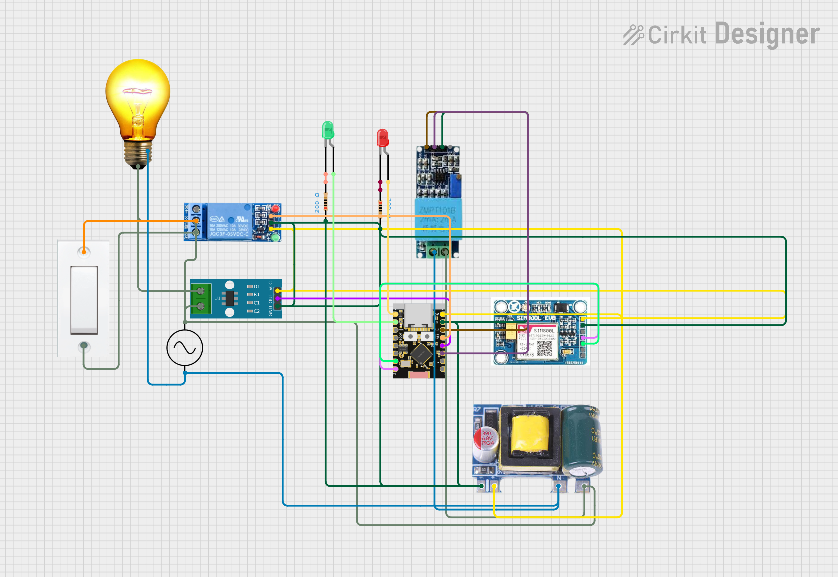
Circuit Documentation
Summary
This circuit is designed to read voltage and current sensors to calculate wattage, control an AC bulb wirelessly, and indicate WiFi connection status using LEDs. The red LED indicates a loss of connection, while the green LED indicates a connection. The relay controls the AC bulb based on the web or an app interface. The circuit is controlled by an ESP32C3 microcontroller.
Component List
LED: Two Pin (green)
- Pins: cathode, anode
- Description: Green LED for indicating WiFi connection status.
- Properties: None
LED: Two Pin (red)
- Pins: cathode, anode
- Description: Red LED for indicating WiFi disconnection status.
- Properties: None
Resistor (200 Ohms)
- Pins: pin1, pin2
- Description: Current limiting resistor for LEDs.
- Properties: Resistance: 200 Ohms
Voltage Sensor
- Pins: Ground, Phase, Vcc, Out, Gnd
- Description: Sensor to measure voltage.
- Properties: None
1 Channel Relay 5V
- Pins: VCC, GND, IN, NC, COM, NO
- Description: Relay to control AC bulb.
- Properties: None
Mini AC-DC 110V-230V to 5V 700mA Module
- Pins: GND, 5v, Neutral, Life
- Description: Power supply module to convert AC to 5V DC.
- Properties: None
SIM 800L V2.0 GSM
- Pins: SIM_TXD, VDD, SIM.RXD, 5V/4V, GND, RST
- Description: GSM module for communication.
- Properties: None
AC Bulb
- Pins: P, N
- Description: AC bulb controlled by the relay.
- Properties: None
Ac Supply
- Pins: +ve, -ve
- Description: AC power supply.
- Properties: None
Flush Switch
- Pins: GND, VCC
- Description: Switch to control the relay.
- Properties: None
ACS712 Current Sensor 5A 20A 30A
- Pins: 1, 2, GND, OUT, VCC
- Description: Sensor to measure current.
- Properties: None
ESP32C3 Supermini
- Pins: GPIO05, GPIO06, GPIO07, GPIO08, GPIO09, GPIO10, GPIO20, GPIO21, GPIO00, GPIO01, GPIO02, GPIO03, GPIO04, 3.3V, GND, +5V
- Description: Microcontroller to control the circuit.
- Properties: None
Wiring Details
LED: Two Pin (green)
- cathode: Connected to pin2 of Resistor (200 Ohms)
- anode: Connected to GPIO06 of ESP32C3 Supermini
LED: Two Pin (red)
- cathode: Connected to pin1 of Resistor (200 Ohms)
- anode: Connected to GPIO05 of ESP32C3 Supermini
Resistor (200 Ohms)
- pin1: Connected to cathode of LED: Two Pin (red) and GND net
- pin2: Connected to cathode of LED: Two Pin (green) and GND net
Voltage Sensor
- Ground: Connected to -ve of Ac Supply, Neutral of Mini AC-DC 110V-230V to 5V 700mA Module, and N of AC Bulb
- Phase: Connected to 1 and 2 of ACS712 Current Sensor 5A 20A 30A, NO of 1 Channel Relay 5V, +ve of Ac Supply, Life of Mini AC-DC 110V-230V to 5V 700mA Module, and P of AC Bulb
- Vcc: Connected to 3.3V of ESP32C3 Supermini
- Out: Connected to GPIO02 of ESP32C3 Supermini
- Gnd: Connected to GND net
1 Channel Relay 5V
- VCC: Connected to 5v of Mini AC-DC 110V-230V to 5V 700mA Module, VCC of ACS712 Current Sensor 5A 20A 30A, +5V of ESP32C3 Supermini, and 5V/4V of SIM 800L V2.0 GSM
- GND: Connected to GND net
- IN: Connected to GPIO04 of ESP32C3 Supermini
- NC: Not connected
- COM: Connected to VCC of Flush Switch
- NO: Connected to Phase of Voltage Sensor
Mini AC-DC 110V-230V to 5V 700mA Module
- GND: Connected to GND net
- 5v: Connected to VCC of 1 Channel Relay 5V, VCC of ACS712 Current Sensor 5A 20A 30A, +5V of ESP32C3 Supermini, and 5V/4V of SIM 800L V2.0 GSM
- Neutral: Connected to Ground of Voltage Sensor, -ve of Ac Supply, and N of AC Bulb
- Life: Connected to Phase of Voltage Sensor, 1 and 2 of ACS712 Current Sensor 5A 20A 30A, NO of 1 Channel Relay 5V, +ve of Ac Supply, and P of AC Bulb
SIM 800L V2.0 GSM
- SIM_TXD: Connected to GPIO21 of ESP32C3 Supermini
- VDD: Not connected
- SIM.RXD: Connected to GPIO20 of ESP32C3 Supermini
- 5V/4V: Connected to VCC of 1 Channel Relay 5V, VCC of ACS712 Current Sensor 5A 20A 30A, +5V of ESP32C3 Supermini, and 5v of Mini AC-DC 110V-230V to 5V 700mA Module
- GND: Connected to GND net
- RST: Not connected
AC Bulb
- P: Connected to Phase of Voltage Sensor, 1 and 2 of ACS712 Current Sensor 5A 20A 30A, NO of 1 Channel Relay 5V, +ve of Ac Supply, and Life of Mini AC-DC 110V-230V to 5V 700mA Module
- N: Connected to Ground of Voltage Sensor, -ve of Ac Supply, and Neutral of Mini AC-DC 110V-230V to 5V 700mA Module
Ac Supply
- +ve: Connected to Phase of Voltage Sensor, 1 and 2 of ACS712 Current Sensor 5A 20A 30A, NO of 1 Channel Relay 5V, Life of Mini AC-DC 110V-230V to 5V 700mA Module, and P of AC Bulb
- -ve: Connected to Ground of Voltage Sensor, Neutral of Mini AC-DC 110V-230V to 5V 700mA Module, and N of AC Bulb
Flush Switch
- GND: Connected to 1 and 2 of ACS712 Current Sensor 5A 20A 30A, Phase of Voltage Sensor, NO of 1 Channel Relay 5V, +ve of Ac Supply, Life of Mini AC-DC 110V-230V to 5V 700mA Module, and P of AC Bulb
- VCC: Connected to COM of 1 Channel Relay 5V
ACS712 Current Sensor 5A 20A 30A
- 1: Connected to GND of Flush Switch, Phase of Voltage Sensor, NO of 1 Channel Relay 5V, +ve of Ac Supply, Life of Mini AC-DC 110V-230V to 5V 700mA Module, and P of AC Bulb
- 2: Connected to GND of Flush Switch, Phase of Voltage Sensor, NO of 1 Channel Relay 5V, +ve of Ac Supply, Life of Mini AC-DC 110V-230V to 5V 700mA Module, and P of AC Bulb
- GND: Connected to GND net
- OUT: Connected to GPIO03 of ESP32C3 Supermini
- VCC: Connected to VCC of 1 Channel Relay 5V, 5v of Mini AC-DC 110V-230V to 5V 700mA Module, +5V of ESP32C3 Supermini, and 5V/4V of SIM 800