Arduino UNO Controlled Robot with Ultrasonic Distance Sensing and Line Following Capabilities
Circuit Documentation
Summary
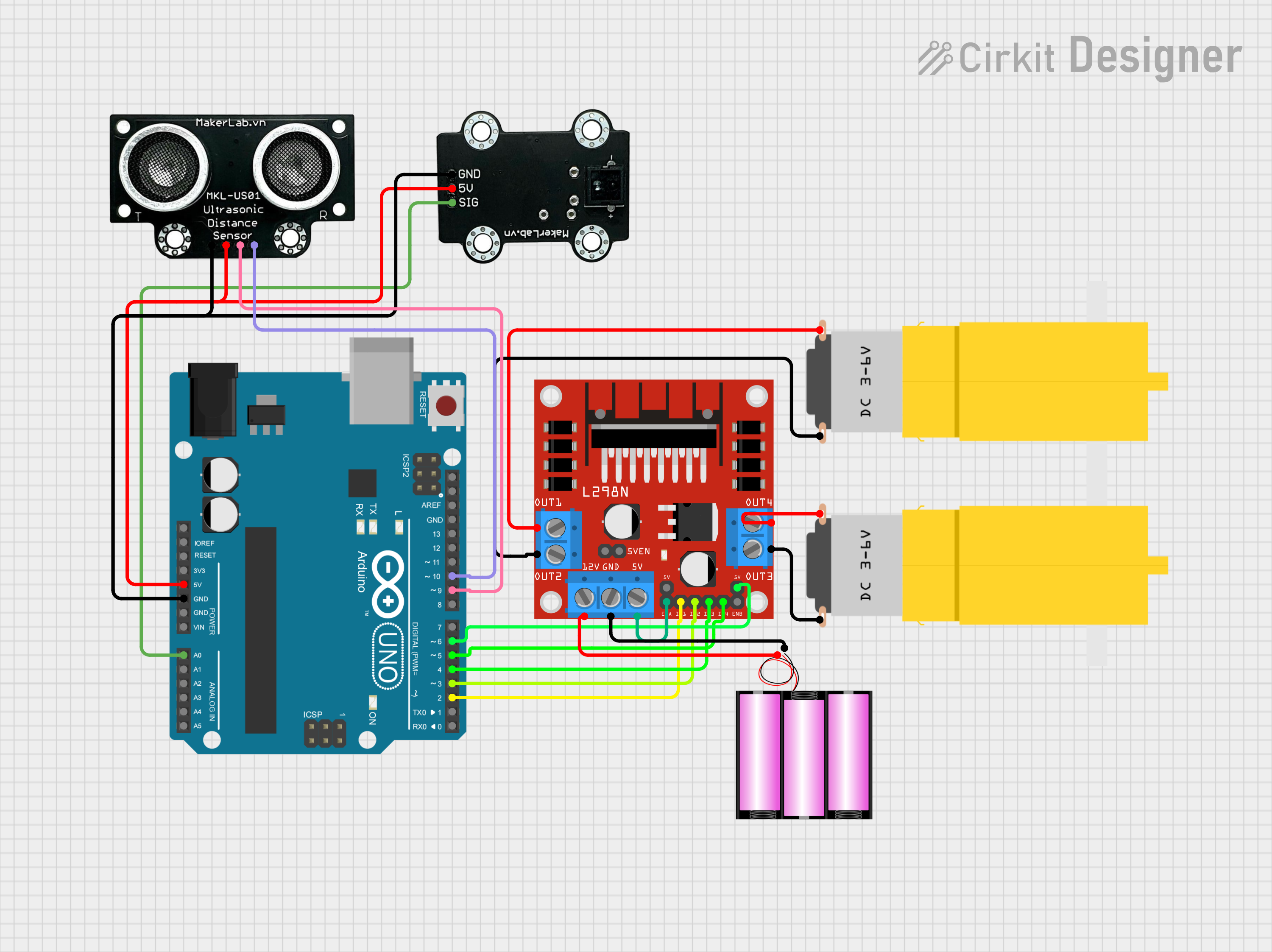
This circuit is designed to control two motors using an L298N DC motor driver, interfaced with an Arduino UNO microcontroller. The circuit also includes an MKE-S01 Ultrasonic Distance Sensor for measuring distances and an MKE-S10 CNY70 Line Follower Sensor for detecting lines. The motors' operations are influenced by the sensors' readings. One motor's activation is based on the line follower sensor, while the other motor's speed is adjusted according to the distance measured by the ultrasonic sensor. The circuit is powered by a 12V battery.
Component List
Arduino UNO
- Microcontroller board based on the ATmega328P
- Provides I/O pins for interfacing with various sensors and the motor driver
MKE-S10 CNY70 Line Follower Sensor
- Optical sensor designed for line tracking
- Outputs a signal that varies depending on the reflectivity of the surface beneath it
MKE-S01 Ultrasonic Distance Sensor
- Sensor that uses ultrasonic waves to measure distance to an object
- Features TRIG and ECHO pins for initiating measurement and receiving the echo
L298N DC Motor Driver
- Module capable of driving two DC motors
- Provides connections for motor power supply and control signals
Motor Amarillo Motorreductor Hobby (x2)
- Hobbyist DC geared motors
- Used for driving wheels or other mechanical parts
Battery 12V
- Provides the power supply for the motor driver and, indirectly, the motors
Wiring Details
Arduino UNO
5VandGNDpins are used to power the MKE-S01 Ultrasonic Distance Sensor and MKE-S10 CNY70 Line Follower Sensor.A0pin is connected to the SIG pin of the MKE-S10 CNY70 Line Follower Sensor.D10pin is connected to the ECHO pin of the MKE-S01 Ultrasonic Distance Sensor.D9pin is connected to the TRIG pin of the MKE-S01 Ultrasonic Distance Sensor.D2toD6pins are used to control the L298N DC Motor Driver.
MKE-S10 CNY70 Line Follower Sensor
SIGpin connected to Arduino UNO'sA0pin.5VandGNDpins connected to the corresponding power supply pins on the Arduino UNO.
MKE-S01 Ultrasonic Distance Sensor
TRIGpin connected to Arduino UNO'sD9pin.ECHOpin connected to Arduino UNO'sD10pin.5VandGNDpins connected to the corresponding power supply pins on the Arduino UNO.
L298N DC Motor Driver
IN1toIN4pins connected to Arduino UNO'sD2toD5pins for motor control signals.ENAandENBpins connected to5Vfor enabling the motor outputs.OUT1toOUT4pins connected to the motors.12VandGNDpins connected to the 12V battery for motor power supply.
Motor Amarillo Motorreductor Hobby
- Each motor has
vccandGNDpins connected to theOUT1/OUT2andOUT3/OUT4pins of the L298N DC Motor Driver, respectively.
Battery 12V
+pin connected to the12Vpin of the L298N DC Motor Driver.-pin connected to theGNDpin of the L298N DC Motor Driver.
Documented Code
/*
 * Arduino Sketch for controlling two motors using an L298 motor driver,
 * an ultrasonic sensor, and a line follower sensor. Motor 1 is activated
 * or stopped based on the line follower sensor, and motor 2's speed is
 * adjusted based on the distance measured by the ultrasonic sensor.
 */

// Pin definitions
const int lineFollowerPin = A0; // Line follower sensor pin
const int trigPin = 9;          // Ultrasonic sensor TRIG pin
const int echoPin = 10;         // Ultrasonic sensor ECHO pin
const int motor1Pin1 = 2;       // Motor 1 control pin 1
const int motor1Pin2 = 3;       // Motor 1 control pin 2
const int motor2Pin1 = 4;       // Motor 2 control pin 1
const int motor2Pin2 = 5;       // Motor 2 control pin 2
const int motor2SpeedPin = 6;   // Motor 2 speed control pin

void setup() {
  // Initialize serial communication
  Serial.begin(9600);

  // Initialize pins
  pinMode(lineFollowerPin, INPUT);
  pinMode(trigPin, OUTPUT);
  pinMode(echoPin, INPUT);
  pinMode(motor1Pin1, OUTPUT);
  pinMode(motor1Pin2, OUTPUT);
  pinMode(motor2Pin1, OUTPUT);
  pinMode(motor2Pin2, OUTPUT);
  pinMode(motor2SpeedPin, OUTPUT);
}

void loop() {
  // Read line follower sensor
  int lineState = analogRead(lineFollowerPin);

  // Control motor 1 based on line follower sensor
  if (lineState < 500) { // Assuming black is low value
    digitalWrite(motor1Pin1, HIGH);
    digitalWrite(motor1Pin2, LOW);
  } else { // Assuming white is high value
    digitalWrite(motor1Pin1, LOW);
    digitalWrite(motor1Pin2, LOW);
  }

  // Measure distance using ultrasonic sensor
  long duration, distance;
  digitalWrite(trigPin, LOW);
  delayMicroseconds(2);
  digitalWrite(trigPin, HIGH);
  delayMicroseconds(10);
  digitalWrite(trigPin, LOW);
  duration = pulseIn(echoPin, HIGH);
  distance = (duration / 2) / 29.1;

  // Control motor 2 speed based on distance
  int motorSpeed = map(distance, 0, 100, 0, 255);
  motorSpeed = constrain(motorSpeed, 0, 255);
  analogWrite(motor2SpeedPin, motorSpeed);
  digitalWrite(motor2Pin1, HIGH);
  digitalWrite(motor2Pin2, LOW);

  // Small delay to stabilize readings
  delay(100);
}
This code is responsible for reading sensor inputs and controlling the motors accordingly. The line follower sensor's signal is read through an analog pin and is used to control the first motor. The ultrasonic sensor's distance measurement is used to adjust the speed of the second motor. The code includes setup routines for pin configurations and a main loop that handles sensor readings and motor control logic.