Arduino UNO Controlled Robotic Arm with Multiple Servos and Pushbutton Control
Circuit Documentation
Summary
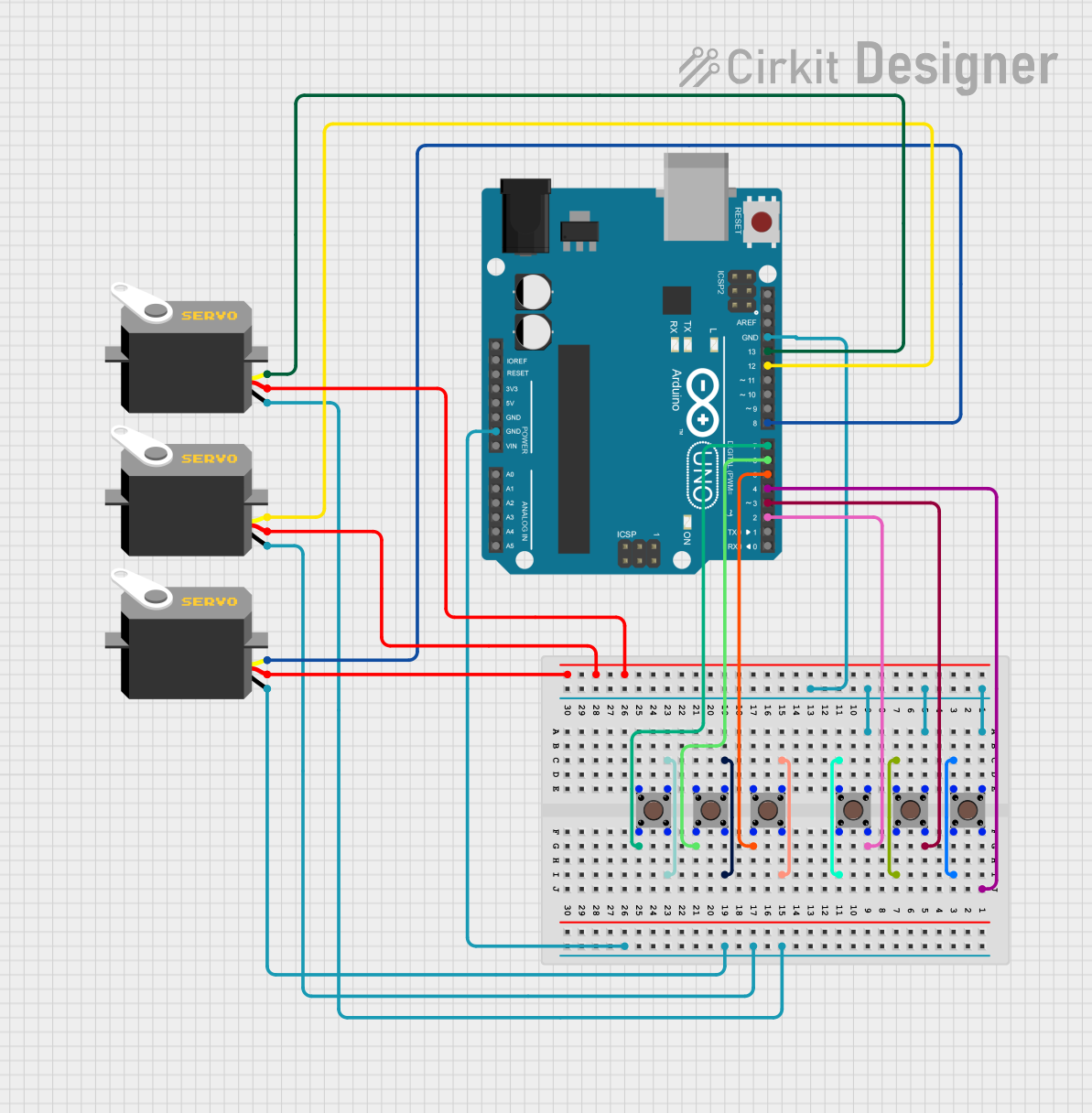
This circuit involves an Arduino UNO microcontroller, multiple pushbuttons, and servos. The Arduino UNO is used to control the servos based on the input from the pushbuttons. The servos are connected to the Arduino UNO and are powered through it. The pushbuttons are used to provide input signals to the Arduino, which then processes these signals to control the servos.
Component List
Arduino UNO
- Description: A microcontroller board based on the ATmega328P.
- Pins: UNUSED, IOREF, Reset, 3.3V, 5V, GND, Vin, A0, A1, A2, A3, A4, A5, SCL, SDA, AREF, D13, D12, D11, D10, D9, D8, D7, D6, D5, D4, D3, D2, D1, D0
Servo (3 units)
- Description: A motor that can be controlled to move to a specific position.
- Pins: gnd, vcc, pulse
Pushbutton (6 units)
- Description: A simple switch mechanism for controlling some aspect of a machine or a process.
- Pins: Pin 3 (out), Pin 4 (out), Pin 1 (in), Pin 2 (in)
Wiring Details
Arduino UNO
- GND: Connected to the GND pins of all servos and the Pin 2 (in) of the first three pushbuttons.
- D4: Connected to Pin 1 (in) of the first pushbutton.
- D3: Connected to Pin 1 (in) of the second pushbutton.
- D2: Connected to Pin 1 (in) of the third pushbutton.
- D5: Connected to Pin 2 (in) of the fourth pushbutton.
- D6: Connected to Pin 2 (in) of the fifth pushbutton.
- D7: Connected to Pin 2 (in) of the sixth pushbutton.
- D13: Connected to the pulse pin of the first servo.
- D12: Connected to the pulse pin of the second servo.
- D8: Connected to the pulse pin of the third servo.
Servo 1
- gnd: Connected to GND of Arduino UNO.
- vcc: Connected to a common power source.
- pulse: Connected to D13 of Arduino UNO.
Servo 2
- gnd: Connected to GND of Arduino UNO.
- vcc: Connected to a common power source.
- pulse: Connected to D12 of Arduino UNO.
Servo 3
- gnd: Connected to GND of Arduino UNO.
- vcc: Connected to a common power source.
- pulse: Connected to D8 of Arduino UNO.
Pushbutton 1
- Pin 1 (in): Connected to D4 of Arduino UNO.
- Pin 2 (in): Connected to GND of Arduino UNO.
- Pin 3 (out): Connected to Pin 4 (out) of the same pushbutton.
- Pin 4 (out): Connected to Pin 3 (out) of the same pushbutton.
Pushbutton 2
- Pin 1 (in): Connected to D3 of Arduino UNO.
- Pin 2 (in): Connected to GND of Arduino UNO.
- Pin 3 (out): Connected to Pin 4 (out) of the same pushbutton.
- Pin 4 (out): Connected to Pin 3 (out) of the same pushbutton.
Pushbutton 3
- Pin 1 (in): Connected to D2 of Arduino UNO.
- Pin 2 (in): Connected to GND of Arduino UNO.
- Pin 3 (out): Connected to Pin 4 (out) of the same pushbutton.
- Pin 4 (out): Connected to Pin 3 (out) of the same pushbutton.
Pushbutton 4
- Pin 2 (in): Connected to D5 of Arduino UNO.
- Pin 3 (out): Connected to Pin 4 (out) of the same pushbutton.
- Pin 4 (out): Connected to Pin 3 (out) of the same pushbutton.
Pushbutton 5
- Pin 2 (in): Connected to D6 of Arduino UNO.
- Pin 3 (out): Connected to Pin 4 (out) of the same pushbutton.
- Pin 4 (out): Connected to Pin 3 (out) of the same pushbutton.
Pushbutton 6
- Pin 2 (in): Connected to D7 of Arduino UNO.
- Pin 3 (out): Connected to Pin 4 (out) of the same pushbutton.
- Pin 4 (out): Connected to Pin 3 (out) of the same pushbutton.
Code Documentation
#include <Wire.h>
#include <Adafruit_PWMServoDriver.h>

#define MIN_PULSE_WIDTH       650
#define MAX_PULSE_WIDTH       2350
#define FREQUENCY             50

Adafruit_PWMServoDriver pwm = Adafruit_PWMServoDriver();

int potWrist = A3;
int potElbow = A2;                        // Assign Potentiometers to pins on Arduino Uno
int potShoulder = A1;
int potBase = A0;

int hand = 11;
int wrist = 12;
int elbow = 13;                           // Assign Motors to pins on Servo Driver Board
int shoulder = 14;
int base = 15;

void setup()
{
  delay(5000);                            // <-- So I have time to get controller to starting position

  pwm.begin();
  pwm.setPWMFreq(FREQUENCY);
  pwm.setPWM(11, 0, 90);                  // Set Gripper to 90 degrees (Close Gripper)

  pinMode(13, INPUT_PULLUP);

  Serial.begin(9600);
}

void moveMotor(int controlIn, int motorOut)
{
  int pulse_wide, pulse_width, potVal;

  potVal = analogRead(controlIn);                                                   // Read value of Potentiometer

  pulse_wide = map(potVal, 800, 240, MIN_PULSE_WIDTH, MAX_PULSE_WIDTH);
  pulse_width = int(float(pulse_wide) / 1000000 * FREQUENCY * 4096);                // Map Potentiometer position to Motor

  pwm.setPWM(motorOut, 0, pulse_width);
}

void loop()
{
  moveMotor(potWrist, wrist);
  moveMotor(potElbow, elbow);                                                       // Assign Motors to corresponding Potentiometers
  moveMotor(potShoulder, shoulder);
  moveMotor(potBase, base);

  int pushButton = digitalRead(13);
  if (pushButton == LOW)
  {
    pwm.setPWM(hand, 0, 180);                             // Keep Gripper closed when button is not pressed
    Serial.println("Grab");
  }
  else
  {
    pwm.setPWM(hand, 0, 90);                              // Open Gripper when button is pressed
    Serial.println("Release");
  }
}
This code initializes the PWM servo driver and sets up the pins for the potentiometers and servos. The moveMotor function maps the potentiometer values to the servo positions. The loop function continuously reads the potentiometer values and updates the servo positions accordingly. Additionally, it reads the state of a pushbutton to control the gripper servo.