
Raspberry Pi Pico Controlled Servo Motor with 10k Ohm Resistor
View and Edit Project In Cirkit Designer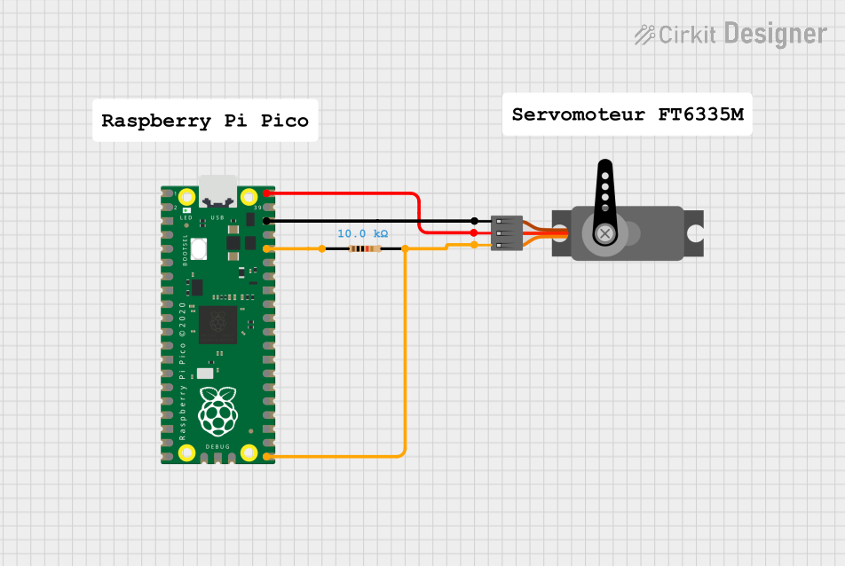
Circuit Documentation
Summary
This document provides a detailed overview of a circuit involving a Raspberry Pi Pico, a Servo motor, and a Resistor. The circuit is designed to control the Servo motor using the Raspberry Pi Pico, with a resistor in place to manage current flow.
Component List
Raspberry Pi Pico
- Description: A low-cost, high-performance microcontroller board with flexible digital interfaces.
- Pins: 43 pins including GPIO, power, and ground pins.
Servo
- Description: A motor that can be precisely controlled in terms of angular position, velocity, and acceleration.
- Pins:
- GND
- VCC
- PWM
Resistor
- Description: A passive electrical component that implements electrical resistance as a circuit element.
- Properties:
- Resistance: 10,000 Ohms
Comment
- Description: Placeholder for comments or notes in the circuit design.
- Pins: None
Wiring Details
Raspberry Pi Pico
- pin 21 is connected to the PWM pin of the Servo and pin2 of the Resistor.
- pin 36 is connected to pin1 of the Resistor.
- pin 38 is connected to the GND pin of the Servo.
- pin 40 is connected to the VCC pin of the Servo.
Servo
- PWM pin is connected to pin 21 of the Raspberry Pi Pico and pin2 of the Resistor.
- GND pin is connected to pin 38 of the Raspberry Pi Pico.
- VCC pin is connected to pin 40 of the Raspberry Pi Pico.
Resistor
- pin1 is connected to pin 36 of the Raspberry Pi Pico.
- pin2 is connected to the PWM pin of the Servo and pin 21 of the Raspberry Pi Pico.
Documented Code
Raspberry Pi Pico Code
void setup() {
  // put your setup code here, to run once:

}

void loop() {
  // put your main code here, to run repeatedly:

}
Documentation File
This documentation provides a comprehensive overview of the circuit, including the components used, their connections, and the code running on the Raspberry Pi Pico.