Cirkit Designer
Your all-in-one circuit design IDE
Home /
Project Documentation
Arduino Nano-Based Smart Sensor System with Ultrasonic and IR Sensors, RGB LED Strip, and Battery Power
Circuit Documentation
Summary
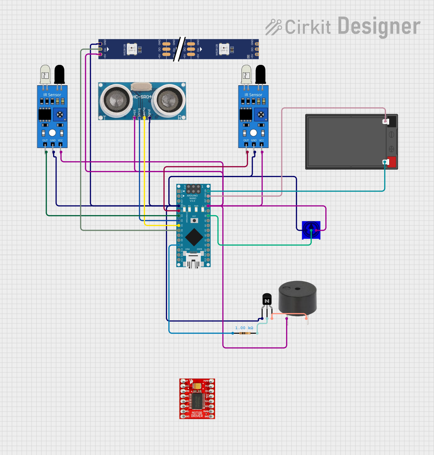
This document provides a detailed overview of a circuit that includes an Arduino Nano microcontroller, various sensors (IR and Ultrasonic), a WS2812 RGB LED strip, a buzzer, a potentiometer, a motor driver, and a 12V battery. The circuit is designed to interface these components with the Arduino Nano to perform various sensing and actuation tasks.
Component List
Arduino Nano
- Description: A small, complete, and breadboard-friendly board based on the ATmega328P.
- Pins: D1/TX, D0/RX, RESET, GND, D2, D3, D4, D5, D6, D7, D8, D9, D10, D11/MOSI, D12/MISO, VIN, 5V, A7, A6, A5, A4, A3, A2, A1, A0, AREF, 3V3, D13/SCK
Ultrasonic Sensor
- Description: A sensor used to measure distance by using ultrasonic waves.
- Pins: +VCC, Trigger, Echo, GND
IR Sensor
- Description: An infrared sensor used for detecting objects.
- Pins: out, gnd, vcc
Buzzer
- Description: An audio signaling device.
- Pins: PIN, GND
NPN Transistor (CBE)
- Description: A transistor used for switching and amplification.
- Pins: collector, base, emitter
Resistor
- Description: A passive electrical component with a resistance of 1000 Ohms.
- Pins: pin1, pin2
WS2812 RGB LED Strip
- Description: An addressable RGB LED strip.
- Pins: DIN, 5V, GND, DO
TSR-3386UT Square Trimming Potentiometer
- Description: A variable resistor used to adjust resistance.
- Pins: Leg1, wiper, Leg2
12V 7Ah Battery
- Description: A rechargeable battery providing 12V.
- Pins: 12v +, 12v -
TB6612FNG Motor Driver
- Description: A motor driver used to control motors.
- Pins: GND, B01, B02, A02, A01, VCC, VM, PWMB, BI2, BI1, STBY, AI1, AI2, PWMA
Wiring Details
Arduino Nano
- GND: Connected to GND of IR sensors, WS2812 RGB LED strip, Ultrasonic Sensor, Potentiometer, and the collector of the NPN Transistor.
- D2: Connected to the out pin of the first IR sensor.
- D3: Connected to the out pin of the second IR sensor.
- D4: Connected to the Trigger pin of the Ultrasonic Sensor.
- D5: Connected to the Echo pin of the Ultrasonic Sensor.
- D6: Connected to the DIN pin of the WS2812 RGB LED strip.
- D9: Connected to pin1 of the Resistor.
- VIN: Connected to 12v + of the 12V 7Ah Battery.
- 5V: Connected to vcc of IR sensors, WS2812 RGB LED strip, Ultrasonic Sensor, PIN of the Buzzer, and Leg2 of the Potentiometer.
- A6: Connected to the wiper of the Potentiometer.
Ultrasonic Sensor
- GND: Connected to GND of the Arduino Nano.
- Trigger: Connected to D4 of the Arduino Nano.
- Echo: Connected to D5 of the Arduino Nano.
- +VCC: Connected to 5V of the Arduino Nano.
IR Sensor (First)
- gnd: Connected to GND of the Arduino Nano.
- out: Connected to D2 of the Arduino Nano.
- vcc: Connected to 5V of the Arduino Nano.
IR Sensor (Second)
- gnd: Connected to GND of the Arduino Nano.
- out: Connected to D3 of the Arduino Nano.
- vcc: Connected to 5V of the Arduino Nano.
Buzzer
- PIN: Connected to 5V of the Arduino Nano.
- GND: Connected to the emitter of the NPN Transistor.
NPN Transistor (CBE)
- collector: Connected to GND of the Arduino Nano.
- base: Connected to pin2 of the Resistor.
- emitter: Connected to GND of the Buzzer.
Resistor
- pin1: Connected to D9 of the Arduino Nano.
- pin2: Connected to the base of the NPN Transistor.
WS2812 RGB LED Strip
- DIN: Connected to D6 of the Arduino Nano.
- 5V: Connected to 5V of the Arduino Nano.
- GND: Connected to GND of the Arduino Nano.
TSR-3386UT Square Trimming Potentiometer
- Leg1: Connected to GND of the Arduino Nano.
- wiper: Connected to A6 of the Arduino Nano.
- Leg2: Connected to 5V of the Arduino Nano.
12V 7Ah Battery
- 12v +: Connected to VIN of the Arduino Nano.
- 12v -: Connected to GND of the Arduino Nano.
Documented Code
Arduino Nano Code (sketch.ino)
void setup() {
  // put your setup code here, to run once:

}

void loop() {
  // put your main code here, to run repeatedly:

}
Additional Documentation (documentation.txt)
This document provides a comprehensive overview of the circuit, including the components used, their connections, and the code running on the Arduino Nano.